Toyota Corolla (E120): Inspection
1. Cooler thermistor no.1
- Check resistance between terminals 1 and 2 of cooler
thermistor no. 1 At each temperature, as shown in the
chart.
Resistance:
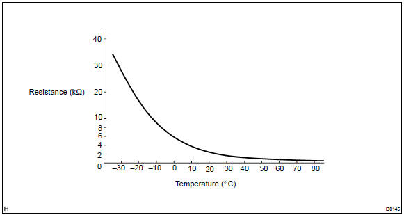
If resistance value is not as specified, replace the sensor.
2. Cooler and accessory assy
- Inspect blower switch continuity.
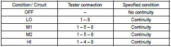
If continuity is not as specified, replace the air conditioner control assy.
- inspect illumination operation.
Connect the positive (+) lead from the battery to terminal 2 and negative (–) lead to terminal 3 then check that the illuminations light up.
If there is bulb not light up, replace the bulb.
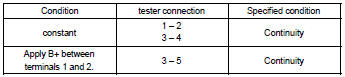
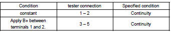
3. Cooler switch hole cover
- Inspect switch continuity.
Check the continuity between terminals while switch is pressed, as shown in the chart.

If continuity is not as specified, replace the cooler switch.
- inspect illumination operation.
Connect the positive (+) lead from the battery to terminal 4 and negative (–) lead to terminal 3 then check that the illuminations light up.
If operation is not as specified, replace the cooler switch.
- inspect indicator operation.
- Connect the positive (+) lead from the battery to terminal 2 and the negative (–) lead to terminal 1.
- Push the a/c button in and then check that the indicator lights up.
If operation is not as specified, replace the cooler switch.
- inspect dimming operation
- connect the positive (+) lead from the battery to terminal 2 and the negative (–) lead to terminal 1 while press the switch.
- Connect the positive (+) lead from battery to terminal 4 and then check that the indicator dims.
If operation is not as specified, replace the cooler switch.
4. Blower resistor
- Measure resistance between terminals, as shown in the chart below.
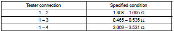
If resistance is not as specified, replace the blower resistor.
5. Blower w/fan motor sub–assy
- Connect the positive (+) lead from the battery to terminal 2 and negative (–) to terminal 1, then check that the motor operation smoothly.
If operation is not as specified, replace the blower motor.
6. Heater blower motor relay assy
If continuity is not as specified, replace the heater blower motor relay.
7. Magnet–clutch relay
If continuity is not as specified, replace the magnet–clutch relay.


Other materials:
Selecting wheel set (vehicles
with a tire pressure
warning system)
Your vehicle is equipped with a
tire pressure warning system
with a function to register two
sets of ID codes. This allows for
registration of a second wheel
set, for example a winter set.
The wheel set can be changed
only if a second wheel set has
been registered to the system. If
a second wheel s ...
Malfunction in tachometer
Wiring diagram
Inspection procedure
Check output value of ecm.
Connect the hand–held tester to dlc3.
Turn the ignition switch to on and push the hand–held tester main switch
on.
Select the data list mode on the hand–held tester.
2 Inspect combinatio ...
Road test
1. Problem symptom confirmation
Taking into consideration the results of the customer problem analysis,
try to reproduce the symptoms
of the trouble. If the problem is that the transaxle does not shift up,
shift down, or the shift point is too
high or too low conduct the following road ...