Toyota Corolla (E120): Hydraulic test
1. Perform hydraulic test
- Measure the line pressure.
Notice
:
- Do the test at normal operation atf temperature 50 to 80 °c (122 to 176 °f).
- The line pressure test should always be carried out in pairs. One technician should observe the conditions of wheels or wheel stopper outside the vehicle while the other is doing the test.
- Be careful to prevent sst’s hose from interfering with the exhaust pipe.
- Warm up the atf.
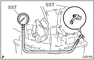
- Remove the test plug on the transaxle case front left
side and connect sst.
Sst 09992–00095 (09992–00231, 09992–00271)
- fully apply the parking brake and chock the 4 wheels.
- Connect an obd ii scan tool or hand–held tester to the dlc3.
- Start the engine and check the idling speed.
- Keep your left foot pressed firmly on the brake pedal and shift into the d position.
- Measure the line pressure when the engine is idling.
- Depress the accelerator pedal all the way down.
Quickly read the highest line pressure when the engine speed reaches the stall speed.
- Do the test in the r position in the same way.
Specified line pressure:

Evaluation:
|
Problem |
Possible cause |
| If the measured values at all positions are higher |
|
| If the measured values at all positions are lower |
|
| If pressure is low in the d position only |
|
| If pressure is low in the r position only |
|


Other materials:
Setting speed dials
1 Select “Add SD” using . 2 Select
the desired data using .
3 Press and hold the desired preset button (from
to
).
For details about setting speed dials from the call history: For details about
deleting speed dials: ...
Data list/active test
1. Data list
Hint:
using the data list displayed by the hand–held tester or the obd ii scan tool,
you can read the value of
the switches, sensors, actuators and so on without parts removal. Reading the
data list as a first step
of troubleshooting is one method to shorten diagnostic time.
...
Check mode procedure
Hint:
hand–held tester only:
compared to the normal mode, the check mode has more sensing
ability to detect malfunctions. Furthermore, the same diagnostic
items which are detected in the normal mode can also be
detected in the check mode.
1. Check mode procedure(using the hand–held tester) ...