Toyota Corolla (E120) 2002–2008 Repair Manual / Introduction / How to use this manual
Toyota Corolla (E120): How to use this manual
General information
1. General description
- This manual is made in accordance with sae j2008.
- generally, repair operations can be separated in the following 3 main processes:
- Diagnosis
- Removing/installing, replacing, disassembling/reassembling, checking and adjusting
- Final inspection
- this manual explains the 1st process of ”diagnosis” (found in the ”diagnostics” section), the 2nd process of ”removing and installing, replacing, disassembling, installing and checking, and adjusting”, but the 3rd process of ”final inspection” is omitted.
- the following essential operations are not written in this manual. However, these operations must be performed in actual situations
- Operations with a jack or lift
- cleaning of a removed part when necessary
- visual check
2. Index
- An alphabetical index section is provided at the end of the book as a reference to help you find the item to be repaired.
3. Preparation
- Use of special service tools (sst) and special service materials (ssm) may be required, depending on the repair situation. Be sure to use sst and ssm when they are required and follow the working procedure properly. A list of sst and ssm is in the preparation section of this manual.
4. Repair procedures
- Component drawing is placed under the title where necessary.
- non–reusable parts, grease application area, precoated parts and tightening torque are specified in the component drawings.
Example:
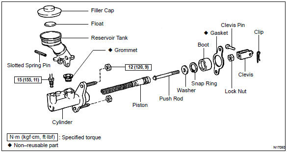
- Tightening torque, grease application area, and non–reusable parts are described as important points in the procedures.
Notice
: there are cases where such information can only be explained by using an illustration. In these cases, all the information such as torque, oil, etc. Are described in the illustration.
- Installing procedures are performed in the reverse order of the removal and only the important points are described.
- only items with points are described in the procedure, and the operational portion and content are placed using an illustration. In the explanations, details of the operational method, standard value and notices are placed.
- there may be a case where the illustrations of similar models are used. In that case, specific details may be different from the actual vehicle.
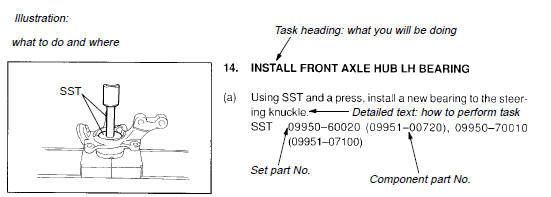
- the procedures are presented in a step–by–step format:
- the illustration shows what to do and where to do it.
- The task heading tells what to do.
- The explanation text tells how to perform the task and gives other information such as specifications and warnings.
Example:
Hint: this format provides an experienced technician with a fast track to the necessary information. The task heading can be read at a glance when necessary and the text below provides detailed information. Important specifications and warnings always are written in bold type to stand out from the rest of the text.
5. Service specifications
- Specifications are presented in bold type throughout the manual. You never have to leave the procedure to look up your specifications. The specifications are also found in the service specifications section for quick reference.
6. Terms definition
| Caution | Indicates the possibility of injury to you or other people. |
| Notice | Indicates the possibility of damage to the components being repaired. |
| Hint | Provides additional information to help you to perform the repair efficiently. |
7. Si unit
- The units given in this manual are primarily expressed according to the si unit (international system of units), and alternately expressed in the metric system and in the english system.
Example
: torque: 30 nvm (310 kgf·cm, 22 ftvlbf)


Other materials:
Replacement
Hint: components:
1. Precaution
2. Disconnect battery negative terminal
3. Remove air bag front rh sensor
Disconnect the connector from the airbag front rh sensor.
remove the 2 bolts and airbag front rh sensor.
4. Inspect air bag front rh sensor
5. Install air bag front rh ...
Circuit description
A flat type knock sensor (non–resonant type) has the structure that can
detect the vibration in a wider band
of frequency from about 6 khz to 15 khz and has the following features.
Knock sensors are fitted on the cylinder block to detect the engine knocking.
The sensor contains a piezoele ...
Basic inspection
When the malfunction is not confirmed in the dtc check, troubleshooting
should be carried out in all the
possible circuits considered as causes of the problem. In many cases, by
carrying out the basic engine check
shown in the following flowchart, the location causing the problem can be found ...