Toyota Corolla (E140) 2007–2013 Body Repair Manual / Body dimensions / General information
Toyota Corolla (E140): General information
1. Basic dimensions
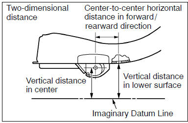
(a) there are two types of dimensions in the diagram.
(1) (Three-dimensional distance)
- straight-line distance between the centers of two measuring points.
(2) (Two-dimensional distance)
- horizontal distance in forward/rearward direction between the centers of two measuring points.
- The height from an imaginary datum line.
(B) in cases in which only one dimension is given, left and right are symmetrical.
(C) the dimensions in the following drawing indicate actual distance.
Therefore, please use the dimensions as a reference.
(D) the line that connects the places listed below is the imaginary datum line when measuring the height. (The dimensions are printed in the text.)

| Symbol | Name |
| 1 | The place that was lowered a mm from the under surface of the rocker panel centered on the front jack up point. |
| 2 | The place that was lowered b mm from the under surface of the rocker panel centered between 1 and 3. |
| 3 | The place that was lowered c mm from the under surface of the rocker panel centered on the rear jack up point. |
2. Measuring
(a) basically, all measurements are to be done with a tracking gauge. For portions where it is not possible to use a tracking gauge, a tape measure should be used.
(B) use only a tracking gauge that has no looseness in the body, measuring plate, or pointers.
Hint:
- the height of the left and right pointers must be equal.
- Always calibrate the tracking gauge before measuring or after adjusting the pointer height.
- Take care not to drop the tracking gauge or otherwise shock it.
- Confirm that the pointers are securely in the holes.
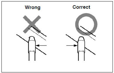
(C) when using a tape measure, avoid twists and bends in the tape.


Other materials:
Cd cannot be taken out
Wiring diagram
Inspection procedure
1 Check if radio auto–search functions properly
Check if the radio auto–search function properly.
Perform the auto–research of the radio and check that the
operation is normal.
Standard: malfunction disappear.
2 Press ”eject†...
Unlocking and locking the doors from the inside
◆ Door lock switches
1 Locks all the doors
2 Unlocks all the doors
◆ Inside lock buttons
1 Locks the door
2 Unlocks the door
The front doors can be opened by pulling the inside handle even if the lock buttons
are in the lock position.
...
Circuit description
Refer to dtc p0115
Dtc no.
Dtc detection condition
Trouble area
P0125
If the engine coolant temperature (ect) was less than –6.6 °C
(20 °F) when starting the engine, and 20 minutes after the engine
start, the ect sensor still indicates below 20 °C (68 ...