Toyota Corolla (E120) 2002–2008 Repair Manual / Introduction / Repair instruction / Precaution / Electronic control
Toyota Corolla (E120): Electronic control
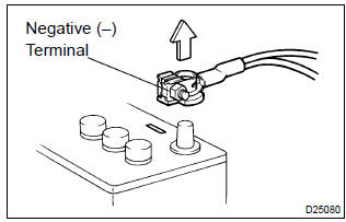
- Removal and installation of battery terminal
- before performing electrical work, disconnect the battery negative (–) terminal cable beforehand so as to prevent burnt–out damage by short.
- When disconnecting and installing the terminal cable, turn the ignition switch and lighting switch off, and loosen the terminal nut completely. Perform these operations without twisting or prying the terminal.
- When the battery terminal is removed, all the memories
of the clock, radio, dtcs, etc. Will be erased.
So before removing it, check them and note them down.
- Handling of electronic parts
- do not open the cover or case of the ecu unless absolutely necessary (if the ic terminals are touched, the ic may be destroyed by static electricity).
- To disconnect electronic connectors, pull the connector itself, not the wires.
- Be careful not to drop electronic components, such as sensors or relays. If they are dropped on a hard floor, they should be replaced and not be reused.
- When cleaning the engine with steam, protect the electronic components, air filter and emission–related components from water.
- Never use an impact wrench to remove or install temperature switches or temperature sensors.
- When checking the continuity at the wire connector, insert the tester probe carefully to prevent terminals from bending.


Other materials:
Selecting a folder
■ Selecting a folder
Press (
) or (
) to select the desired folder.
■ Selecting a folder and file from a folder list
1 Press .
A folder list will be displayed.
2 Turn and press to select a folder
and a file.
To return to the previous display, press
(BACK).
■ Return ...
Windshield wiper switch assy
Replacement
1. Remove steering column cover lwr
Remove 3 screws and steering column cover lwr.
2. Remove windshield wiper switch assy
Disconnect the connecter of the windshield wiper switch.
release the claw and pull out the windshield wiper switch
assy as shown in the ...
On–vehicle inspection
1. Washer motor
Operation check
pour the water into the washer jar with the washer
motor and the pump installed to the washer jar assy.
Connect the battery (+) to terminal 2 of the washer
motor and the pump, the battery (–) to terminal 1 of
the washer motor and the pump ...