Toyota Corolla (E120) 2002–2008 Repair Manual / Diagnostics / Audio system / Diagnostic trouble code chart
Toyota Corolla (E120): Diagnostic trouble code chart
|
Terms |
Terms |
| Physical address | Three–digit code (shown in hexadecimal) which is given to each
component comprising
the avc–lan.
Corresponding to the function, individual symbols are specified. |
| Logical address | Two–digit code (shown in hexadecimal) which is given to each function comprising the inner system of the avc–lan. |
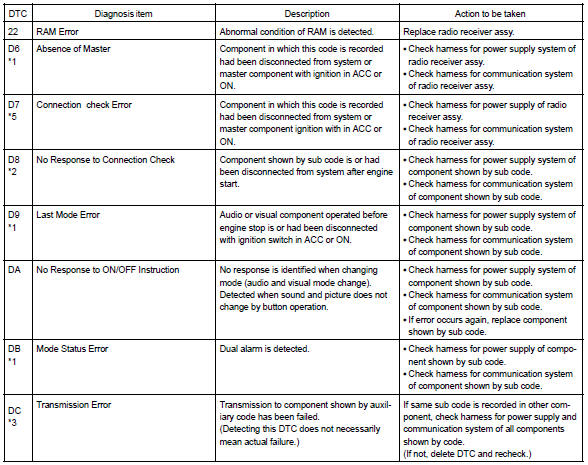
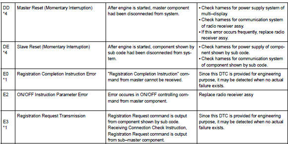
1. Radio receiver assy (physical address: 190)
Hint
: *1: even if no failure is detected, it may be stored depending on the battery condition or voltage for starting an engine.
*2: It is stored when 180 sec. Has passed after the power supply connector is pulled out after engine start.
*3: It may be stored when the engine key is turned 1 min. After engine start.
*4: It may be stored when the engine key is turned again after engine start.
*5: When 210 sec. Has passed after pulling out the power supply connector of the master component with the ignition switch in acc or on, this code is stored.
- Logical address: 01 (communication control)
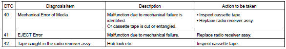
- Logical address: 61 (cassette switch)
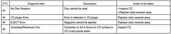
- Logical address: 62 (cd player)
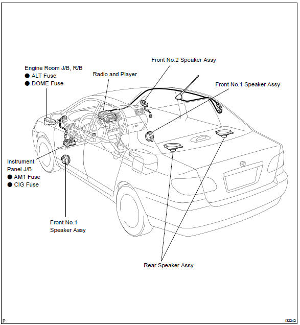
Location


Other materials:
Front differential oil seal
Replacement
1. Drain manual transaxle oil
torque: 39.2 Nvm (400 Kgf·cm, 29 ft·lbf)
2. Remove front wheels
3. Remove engine under cover lh
4. Remove engine under cover rh
5. Drain transaxle oil
6. Remove front drive shaft assy lh
sst 09520–01010, 09520–24010 (09520–32040)
7. R ...
Inspection procedure
1 Check fuse(ecu–ig)
Remove the ecu–ig fuse from the instrument panel j/b.
check the continuity of the ecu–ig fuse.
Ok: continuity
2 Inspect terminal voltage(b)
Remove the cruise control ecu assy with connector still
connected.
turn the ignition switch ...
Cooling
Preparation
Recomended tools
Equipment
Coolant
...