Toyota Corolla (E120) 2002–2008 Repair Manual / Introduction / How to troubleshoot ecu controlled
systems / Diagnostic trouble code chart
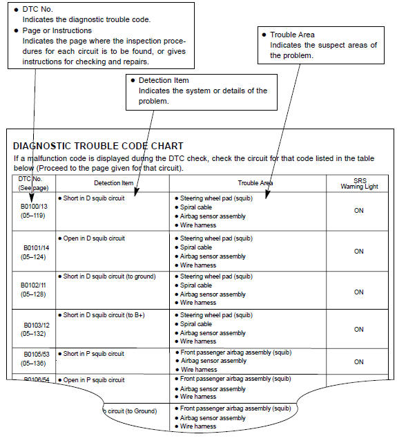
Toyota Corolla (E120): Diagnostic trouble code chart
The inspection procedures are shown in the table below. This table allows efficient and accurate troubleshooting using the diagnostic trouble codes displayed in the diagnostic trouble code chart. Proceed with troubleshooting in accordance with the inspection procedures listed in the diagnostic chart corresponding to the diagnostic trouble codes displayed. The diagnostic trouble code chart for the supplemental restraint system is shown below as an example.


Other materials:
Eco Driving Indicator Light customization (except vehicles with a manual transmission)
Eco Driving Indicator Light can be activated or deactivated.
1 While the odometer is being displayed, press and hold the “DISP” switch to
display the Eco Driving Indicator Light customization screen.
2 Press the “DISP” switch to set Eco Driving Indicator Light to on or off.
3 Press and ...
Inspection procedure
1 Check door lock
2 Check wire harness (tvip ecu door lock)
Disconnect the tvip ecu and door lock connectors.
check the continuity between the terminals of the tvip
ecu and door lock connectors, as shown in the illustration
and table.
Standard:
3 Check wire harness ...
Body panel sealing areas
Be sure to apply body sealer to the body panel joints and door edges (tip of
outer panel folded part), etc., To waterproof
and rustproof them.
Hint:
apply degreasing agent to a clean cloth and clean the sealer
application areas.
After removing the applied spot sealer from the se ...