Toyota Corolla (E120) 2002–2008 Repair Manual / Diagnostics / Sfi system / Random/multiple cylinder misfire
detected / Confirmation driving pattern
Toyota Corolla (E120): Confirmation driving pattern
- Connect the hand–held tester or the obd ii scan tool to the dlc3.
- record dtcs and the freeze frame data.
- set the check mode using the hand–held tester .
- read the value on the misfire counter for each cylinder when idling. If the value is displayed on the misfire counter, skip the following procedure of confirmation driving.
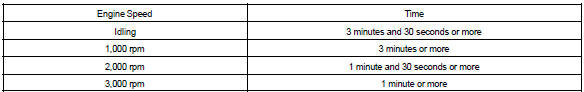
- drive the vehicle several times with the engine speed, load and its surrounding range shown with engine spd, calc load in the freeze frame data or misfire rpm, misfire load in the data list.
If you have no hand–held tester, turn the ignition switch off after the symptom is simulated once. Then repeat the simulation process again.
Hint
: do not turn the ignition switch off during the confirmation driving pattern. This switches the diagnosis system from the check mode to the normal mode, so all the dtcs and freeze frame data will be erased.
- Check whether there is misfire or not by monitoring dtc and the freeze frame data. After that, record them.
- turn the ignition switch off and wait for at least 5 seconds.


Other materials:
Inspection procedure
1 Check fuse(ecu–ig)
Remove the ecu–ig fuse from the instrument panel j/b.
check the continuity of the ecu–ig fuse.
Ok: continuity
2 Inspect terminal voltage(b)
Remove the cruise control ecu assy with connector still
connected.
turn the ignition switch ...
Dtc check/clear
Notice:
if there is no dtc in the normal mode, check the pending
fault code using the continuous test results
function (mode 7 for sae j1979) on the obd ii scan
tool or the hand–held tester.
Hand–held tester only:
when the diagnosis system is switched from the normal
mode to the ...
Overhaul
1. Remove oil filler cap sub–assy
Remove the oil filler cap from the cylinder head cover.
2. Remove oil filler cap gasket
Using a screwdriver, remove the gasket from the oil filler
cap.
3. Remove ventilation valve sub–assy
Remove the ventilation valve from the cyl ...