Toyota Corolla (E120): Circuit inspection
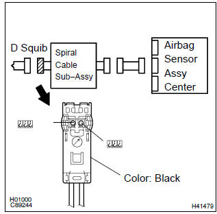
1 Check d squib circuit(airbag sensor assy center – horn button assy)
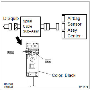
- Disconnect the negative (–) terminal cable from the battery, and wait at least for 90 seconds.
- disconnect the connectors between the airbag sensor assy center and the horn button assy.
- connect the negative (–) terminal cable to the battery, and wait at least for 2 seconds.
- turn the ignition switch to on.
- for the black connector (on the spiral cable sub–assy
side) between the horn button assy and the spiral cable
sub–assy, measure the voltage between d2+ and body
ground.
Ok: voltage: below 1 v


2 Check air bag sensor assy center
Sst 09843–18040
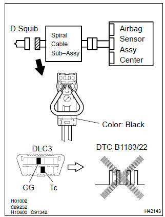
- Turn the ignition switch to lock.
- disconnect the negative (–) terminal cable from the battery, and wait at least for 90 seconds.
- connect the connector to the airbag sensor assy center.
- using a service wire, connect d2+ and d2– of the black connector (on the spiral cable sub–assy side) between the horn button assy and the spiral cable sub–assy.
- connect the negative (–) terminal cable to the battery, and wait at least for 2 seconds.
- turn the ignition switch to on, and wait at least for 20 seconds.
- clear the dtc stored in memory .
- turn the ignition switch to lock, and wait at least for 20 seconds.
- turn the ignition switch to on, and wait at least for 20 seconds.
- check the dtc .
Ok: dtc b1183/22 is not output.
Hint
: codes other than code b1183/22 may be output at this time, but they are not relevant to this check.


3 Check d squib
Sst 09843–18040
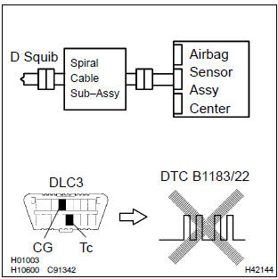
- Turn the ignition switch to lock.
- disconnect the negative (–) terminal cable from the battery, and wait at least for 90 seconds.
- connect the horn button assy connectors.
- connect the negative (–) terminal cable to the battery, and wait at least for 2 seconds.
- turn the ignition switch to on, and wait at least for 20 seconds.
- clear the dtc stored in memory .
- turn the ignition switch to lock, and wait at least for 20 seconds.
- turn the ignition switch to on, and wait at least for 20 seconds.
- check the dtc .
Ok: dtc b1183/22 is not output.
Hint
: codes other than code b1183/22 may be output at this time, but they are not relevant to this check.


4 Use simulation method to check


Replace all srs components including the wire harness
5 Check instrument panel wire(airbag sensor assy center – spiral cable sub–assy)
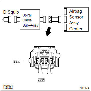
- Turn the ignition switch to lock.
- disconnect the connector of the instrument panel wire.
- turn the ignition switch to on.
- ) for the connector (on the spiral cable sub–assy side) between
the horn button assy and the spiral cable sub–assy,
measure the voltage between d2+ and body ground.
Ok: voltage: below 1 v

6 Check spiral cable sub–assy
- For the black connector (on the spiral cable sub–assy
side) between the horn button assy and the spiral cable
sub–assy, measure the voltage between d2+ and body
ground.
Ok: voltage: below 1 v


7 Use simulation method to check


Replace all srs components including the wire harness


Other materials:
Meter display
■ Locations of gauges and meters
The units of measure may differ depending on the intended destination of
the vehicle.
Tachometer
Displays the engine speed in revolutions per minute
Outside temperature
Displays the outside temperature within the range of -40ºF (-40ºC) to 140ºF
(60ºC)
...
Inspection procedure
1 Check p squib circuit(airbag sensor assy center – instrument
panel passenger airbag assy)
Disconnect the negative (–) terminal cable from the battery,
and wait at least for 90 seconds.
disconnect the connectors between the airbag sensor
assy center and the instrument panel ...
Listening to a USB memory device
Connecting a USB memory device enables you to enjoy music from the vehicle
speakers.
Touch “USB” on the audio source selection screen.
Connecting a USB memory device
Audio control screen
Pressing the “AUDIO” button displays the audio control screen from any screens
of the selected so ...