Toyota Corolla (E120) 2002–2008 Repair Manual / Diagnostics / Supplemental restraint system / Tc terminal circuit / Circuit description
Toyota Corolla (E120): Circuit description
Dtc output mode is set by connecting between tc and cg of the dlc3.
The dtcs are displayed by blinking the srs warning light.
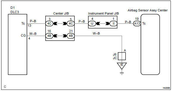
Wiring diagram
Hint
: when each warning light stays blinking, ground short in the wiring until the terminal tc of the dlc3 or internal ground short in each ecu is suspected.


Other materials:
For vehicles equipped with mobile communication system
Install an antenna as far as possible away from the ecu
and sensors of the vehicle’s electronic systems.
install an antenna feeder at least 20 cm (7.87 In.) Away
from the ecu and sensors of the vehicle’s electronic systems.
For details of the ecu and sensors locations, refer ...
Problem symptoms table
The suspected circuits or parts for each problem symptom are shown in the
table below. Use this table to
troubleshoot the problem when a normal code is displayed in the diagnostic
trouble code chart but the problem
is still occurring. Numbers in the table indicate the order in which the
circ ...
Removal & installation and disassembly & reassembly
1. Remove oxygen sensor
Remove a clip and tear off the floor mat.
disconnect a oxygen sensor connector.
Remove the oxygen sensor.
2. Remove tail pipe assy
Remove 2 bolts, 2 springs and tail pipe assy.
3. Remove floor panel brace front
Remove 2 nuts and the ...