Toyota Corolla (E120): Circuit description
The p squib (2nd step) circuit consists of the airbag sensor assy center and instrument panel passenger airbag assy.
It causes the srs to deploy when the srs deployment conditions are satisfied.
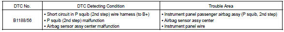
Dtc b1188/56 is recorded when a b+ short is detected in the p squib (2nd step) circuit.
Wiring diagram


Other materials:
Engine oil
With the engine at operating temperature and turned off, check the oil level
on the dipstick.
■ Checking the engine oil
1 Park the vehicle on level ground. After warming up the engine and turning it
off, wait more than 5 minutes for the oil to drain back into the bottom of the engine.
2 ...
Circuit description
The seat belt buckle switch (lh) circuit consists of the airbag sensor assy
center and front seat inner belt
assy (lh).
Dtc b0126/b0127/27 is recorded when a malfunction is detected in the seat belt
buckle switch (lh) circuit.
Wiring diagram
...
Body
On–vehicle inspection
1. Canada:
tighten bolts and nuts on chassis and body
tighten the bolts and nuts on the chassis parts listed below, if
necessary
Front axle and suspension
drive train
rear axle and suspension
brake system
engine mounting
other chassis parts
...