
Toyota Corolla (E120) 2002–2008 Repair Manual / Diagnostics / Supplemental restraint system / Short in side squib (rh) circuit / Circuit description
Toyota Corolla (E120): Circuit description
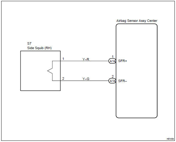
The side squib (rh) circuit consists of the airbag sensor assy center and front seat airbag assy (rh).
It causes the srs to deploy when the srs deployment conditions are satisfied.
Dtc b0110/43 is recorded when a short is detected in the side squib (rh) circuit.

Wiring diagram


Other materials:
Screen for general settings
1 Press the “SETUP” button.
2 Select “General” on the “Setup” screen.
1 “English”, “Français” or “Español” can be selected.
2 On/off can be selected to sound beeps.
3 Select to change the screen color.
4 Select to change the keyboard layout.
5 The animatio ...
Hydraulic test
1. Perform hydraulic test
Measure the line pressure.
Notice:
Do the test at normal operation atf temperature 50 to 80 °c (122 to
176 °f).
The line pressure test should always be carried out in pairs. One
technician should observe
the conditions of wheels or wheel stopper outsi ...
Smart key system
The following operations
can be performed simply by
carrying the electronic key
on your person, for example
in your pocket. The driver
should always carry the
electronic key.
Locks and unlocks the
doors
Opens the trunk
Starts the engine
■Antenna location
Antennas outside the cabin
Ante ...