Toyota Corolla (E120) 2002–2008 Repair Manual / Diagnostics / Sfi system / Stop light switch circuit / Circuit description
Toyota Corolla (E120): Circuit description
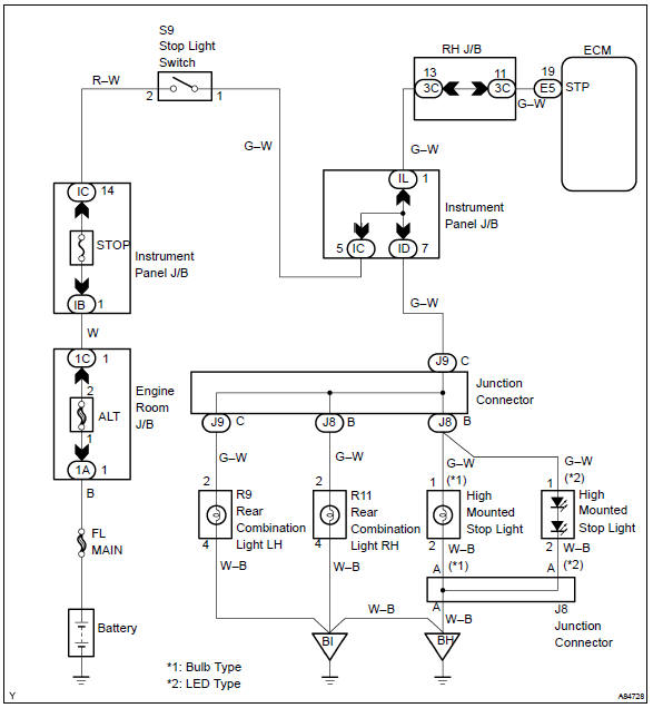
This signal is used to detect that the brakes have been applied. The stp signal voltage is the same as the one supplied to the stop lights.
The stp signal is used mainly to control the fuel cut–off engine speed (the fuel cut–off engine speed is reduced slightly when the vehicle is braking.).
Wiring diagram


Other materials:
Vehicle information
This screen can be used to display the fuel consumption.
“Trip Information” or “Past Record” screen
Press “CAR” to display the “Trip Information” or “Past Record” screen.
Fuel consumption
■ Trip information
If the “Trip Information” screen does not appear, select â ...
Inspection procedure
1 Check p squib circuit(airbag sensor assy center – instrument
panel passenger airbag assy)
Disconnect the negative (–) terminal cable from the battery,
and wait at least for 90 seconds.
disconnect the connector between the airbag sensor
assy center and the instrument panel ...
Monitor description
While the engine is being cranked, the battery positive voltage is applied to
terminal sta of the ecm.
If the ecm detects the starter control signal (sta) while the vehicle is
driving, it will conclude that there is
a fault in the starter control circuit. The ecm will turn on the mil and a d ...