Toyota Corolla (E120) 2002ŌĆō2008 Repair Manual / Diagnostics / Sfi system / Fuel pump control circuit / Circuit description
Toyota Corolla (E120): Circuit description
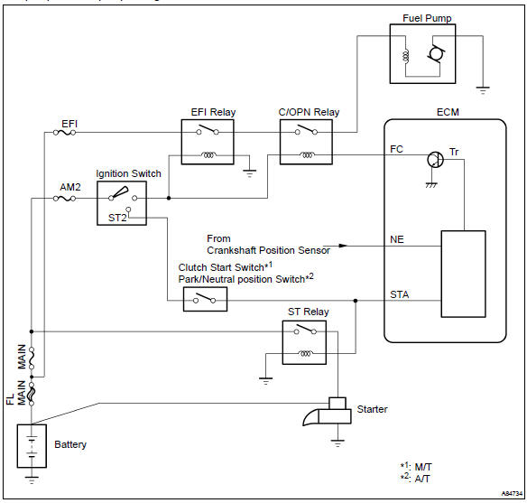
In the diagram below, when the engine is cranked, current flows from terminal st2 of the ignition switch to the starter relay coil and also current flows to terminal sta of the ecm (sta signal).
When the sta signal and ne signal are input to the ecm, tr is turned on, current flows to the coil of the circuit opening relay, the relay switches on, power is supplied to the fuel pump and the fuel pump operates.
While the ne signal is generated (engine running), the ecm keeps tr on (circuit opening relay on) and the fuel pump also keeps operating.
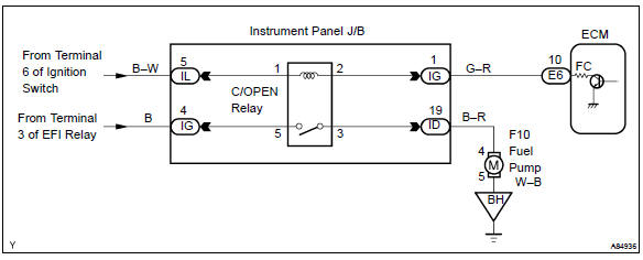
Wiring diagram


Other materials:
How to use this manual
General information
1. General description
This manual is made in accordance with sae j2008.
generally, repair operations can be separated in the following 3
main processes:
Diagnosis
Removing/installing, replacing, disassembling/reassembling,
checking and adju ...
OnŌĆōvehicle inspection
1. Inspect front axle hub bearing
remove the front wheel.
separate the front disc brake caliper assy .
remove the front disc.
inspect the bearing backlash.
Using a dial indicator, check the backlash near the
center of the axle hub.
Maximum: 0.05 Mm (0. ...
How to scroll
: Select to scroll to the next or
previous page.
: If
appears to the right of titles, the
complete titles are too long for the display. Select this button to scroll the title.
Turn the ŌĆ£TUNE/SCROLLŌĆØ knob to move the cursor box to select a desired item from
the list, and press the Ō ...