Toyota Corolla (E120) 2002–2008 Repair Manual / Diagnostics / Sfi system / Idle air control System/ Circuit / Circuit description
Toyota Corolla (E120): Circuit description
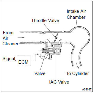
The rotary solenoid type idle air control (iac) valve is located under the throttle body and intake air bypassing the throttle valve flows into the iac valve through the passage.
In this way the intake air volume bypassing the throttle valve is regulated, controls the engine speed.
The ecm operates the iac valve only to perform idle–up and provide feedback for the target idling speed.
Monitor description
The idle speeds are determined depending on the volume of air that passes through the iac valve. When the volume is large, the idle speed becomes higher. When the volume is small, the idle speed becomes lower.
The iac valve controls the air volume that bypasses the throttle valve. The engine control module (ecm) sends duty signals to the iac valve and drives the iac valve stepper motor to determine the air volume that bypasses the throttle valve.
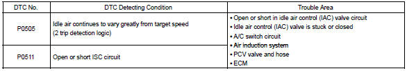
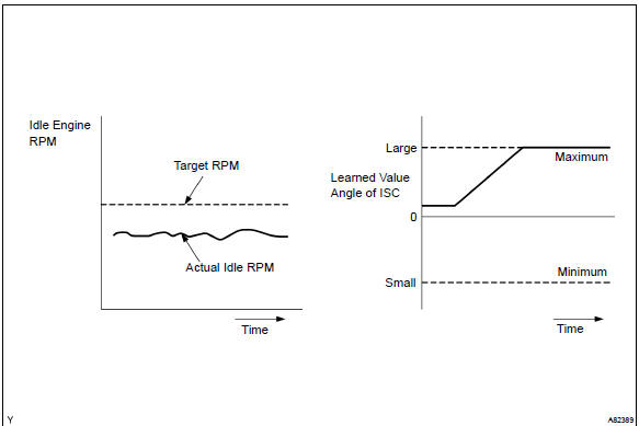
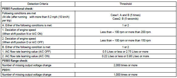
Although the ecm regulates the idle engine rpm with the feedback control in several vehicle stopped, actual idle rpm does not reach the targeted rpm and a learned valve angle of the idle air control (iac) remains at the maximum or remains at the minimum, the ecm determines to detect malfunction in the iac system.
Example: if the rpm difference between the targeted and actual idle engine rpms exceeds 200 rpm (*1) with the vehicle stopped in an idle, and this occurs 5 times, or if the learned value angle of the iac remains at its maximum or minimum angle for 5 seconds, p505 is detected.
P0511 is detected as an open/short circuit in the iac if the rate of duty signal input to the iac valve has stuck at 0 or 100 %.
*1: Threshold rpm is varied by an engine load.
Monitor strategy
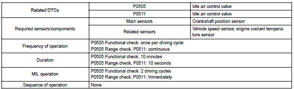
Typical enabling condition
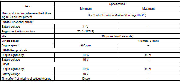
Typical malfunction thresholds
Component operating range

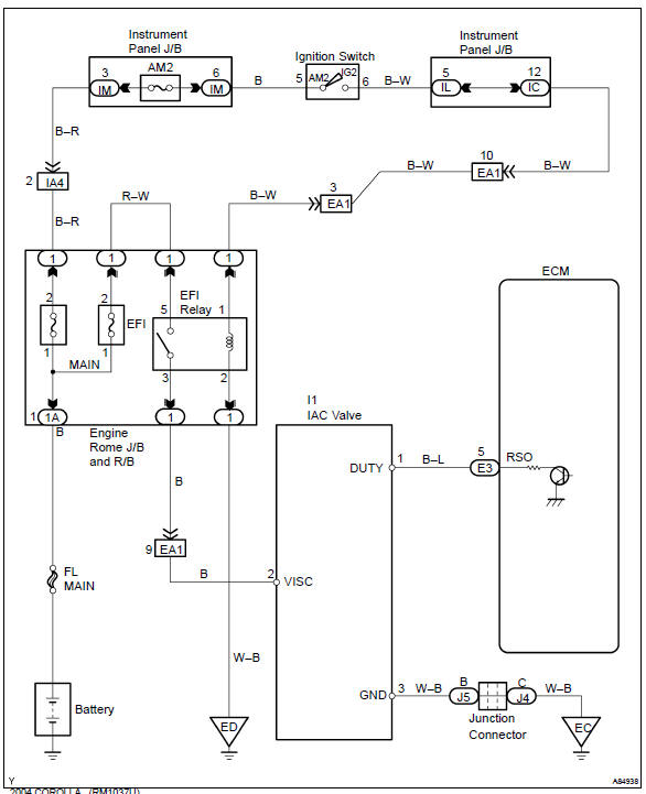
Wiring diagram


Other materials:
Diagnostic trouble code chart
Hint:
when the srs warning light remains lit up and the dtc is the normal
code, this means a voltage source
drops.
This malfunction is not stored in memory by the airbag sensor assy center
and if the power source
voltage returns to normal, the srs warning light will autom ...
Entire combination meter does not operate
Wiring diagram
Inspection procedere
1 Check fuse
Check that continuity exists of dome fuse.
check that continuity exists of gauge fuse.
check that continuity exists of am1 fuse.
2 Inspect combination meter assy
Check continuity.
Disconnect the ” ...
Circuit description
The seat belt buckle switch (lh) circuit consists of the airbag sensor assy
center and front seat inner belt
assy (lh).
Dtc b0126/b0127/27 is recorded when a malfunction is detected in the seat belt
buckle switch (lh) circuit.
Wiring diagram
...