Toyota Corolla (E120) 2002–2008 Repair Manual / Diagnostics / Sfi system / Vehicle speed sensor ”a” / Circuit description
Toyota Corolla (E120): Circuit description
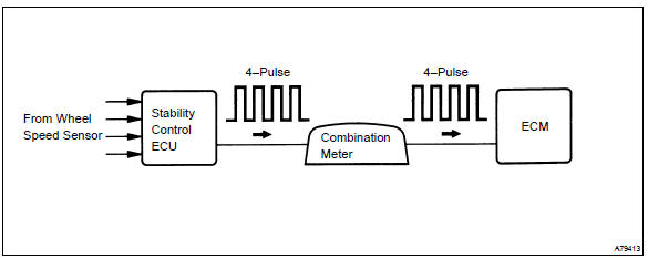
The vehicle equipped with abs detects a vehicle speed using the stability control ecu and wheel speed sensor. This sensor monitors a wheel rotation speed and sends the signal to the ecu.
The stability control ecu converts these wheel speed signals into a 4–pulse signal and outputs it to the ecm via the combination meter.
The ecm determines the vehicle speed based on the frequency of these pulse signals.
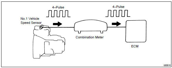
In the vehicle without abs, the no. 1 Vehicle speed sensor outputs a 4–pulse signal for every revolution of the rotor shaft, which is rotated by the transmission output shaft via the driven gear. After this signal is converted into a more precise rectangular waveform by the waveform shaping circuit inside the combination meter, it is then transmitted to the ecm. The ecm determines the vehicle speed based on the frequency of these pulse signal.
W/ abs:
W/o abs:
Monitor description
Equipped with abs:
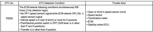
the ecm assumes that the vehicle is driven when the rpm of the transmission counter gear indicates more than 300 rpm and it has been over 30 seconds since the park/neutral position switch was turned off. If there is no signal from the vehicle speed sensor with these conditions satisfied, the ecm concludes that there is a fault in the vehicle speed sensor. The ecm will turn on the mil and a dtc is set.
Not equipped with abs:
the ecm assumes that the vehicle is driven when the park/neutral position switch is off and it has been over 4 seconds since the actual vehicle speed was 9 km/h or more.
If there is no signal from the vehicle speed sensor with these conditions satisfied, the ecm concludes that there is a fault in the vehicle speed sensor. The ecm will turn on the mil and a dtc is set.
Monitor strategy
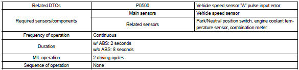
Typical enabling conditions

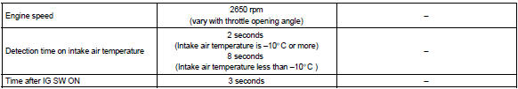
Typical malfunction thresholds

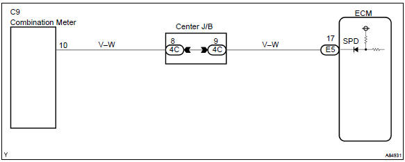
Wiring diagram


Other materials:
Odometer and trip meter
display
■ Changing the display
Press the display change button
until the desired item is displayed.
■ Display items
Odometer
Displays the total distance the vehicle
has been driven.
Trip meter A/Trip meter B
Displays the distance the vehicle
has been driven since the meter
was last reset. Trip ...
Check and replace ecu
Notice:
start an inspection of the connector from the backside
of the connector on the wire harness side with
the connector connected to the ecu.
When no measurement condition is specified, perform
the inspection with the engine stopped and also
the ignition switch on.
First check the ec ...
Inspection procedure
Hint:
hand–held tester only:
narrowing down the trouble area is possible by performing ”a/f control” active
test (heated oxygen
sensor or other trouble areas can be distinguished).
perform active test using hand–held tester (a/f control).
Hint:
”a/f control” is the act ...