Toyota Corolla (E120) 2002–2008 Repair Manual / Diagnostics / Sfi system / Ignition coil primary/secondary
circuit / Circuit description
Toyota Corolla (E120): Circuit description
Hint
:
- these dtcs indicate a malfunction related to the primary circuit.
- If dtc p0351 is displayed, check the no.1 Ignition coil with igniter circuit.
- If dtc p0352 is displayed, check the no.2 Ignition coil with igniter circuit.
- If dtc p0353 is displayed, check the no.3 Ignition coil with igniter circuit.
- If dtc p0354 is displayed, check the no.4 Ignition coil with igniter circuit.
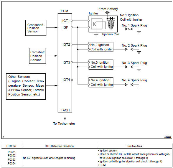
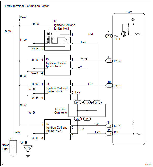
A direct ignition system (dis) is used on this vehicle. The dis improves the ignition timing accuracy, reduces high–voltage loss, and enhances the overall reliability of the ignition system by eliminating the distributor.
The dis is a 1–cylinder ignition system which ignites one cylinder with one ignition coil. In the 1–cylinder ignition system, the one spark plug is connected to the end of the secondary winding. High voltage generated in the secondary winding is applied directly to the spark plug. The spark of the spark plug passes from the center electrode to the ground electrode.
The ecm determines the ignition timing and outputs the ignition signals (igt) for each cylinder. Using the ignition (igt) signal, the ecm turns on and off the power transistor inside the igniter and this switches on and off the current to the primary coil. When the current flow to the primary coil is cut off, high–voltage is generated in the secondary coil and this voltage is applied to the spark plugs to spark inside the cylinders.
As the ecm cuts the current to the primary coil, the igniter sends back the ignition confirmation (igf) signal for each cylinder ignition to the ecm.
Monitor description
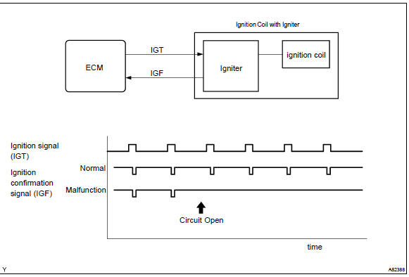
If the ecm does not receive the ignition confirmation signal (igf) after sending the ignition signal (igt), it interprets this as a fault in the igniter and sets a dtc.
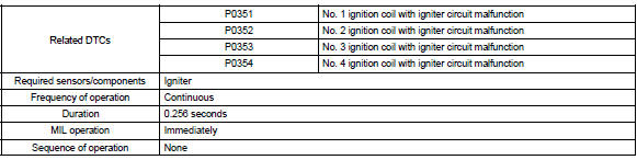
Monitor strategy
Typical enabling conditions
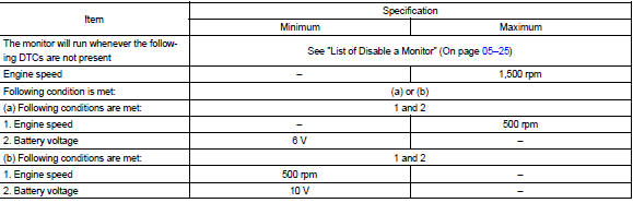
Typical malfunction thresholds

Component operating range

Wiring diagram


Other materials:
Automatic door locking and unlocking systems
The following functions can be set or cancelled:
*1: Vehicles with an automatic transmission or continuously variable transmission
*2: Vehicles with a smart key system
■ Setting and canceling the functions
To switch between set and canceled, follow the procedure below:
1 Vehicles withou ...
Inspection
1. Cooling fan relay
Inspect the cooling fan relay continuity.
Using an ohmmeter, check that there is continuity
between terminals 1 and 2.
If there is no continuity, replace the relay.
Check that there is no continuity between terminals
3 and 5.
If there is conti ...
Have the malfunction repaired immediately. (vehicles with a smart key system)
After taking the specified steps to correct the suspected problem, check that
the warning message and light go off.
■Warning buzzer ...