Toyota Corolla (E120) 2002–2008 Repair Manual / Diagnostics / Sfi system / Camshaft position sensor ”a”
circuit / Circuit description
Toyota Corolla (E120): Circuit description
The camshaft position sensor (g22+ signal) consists of a magnet, iron core and pickup coil.
The g22+ signal plate has 3 teeth on its outer circumference and is installed on the camshaft timing pulley.
When the camshafts rotate, the protrusion on the signal plate and the air gap on the pickup coil changes, causing fluctuations in the magnetic field and generating an electromotive force in the pickup coil.
The ne+ signal plate (crankshaft timing pulley) has 34 teeth and is installed to the crankshaft. The ne+ signal sensor generates 34 signals at every engine revolution. The ecm detects the crankshaft angle and the engine revolution based on the ne+ signals, and the cylinder and the angle of the vvt based on the combination of the g22+ and ne+ signals.
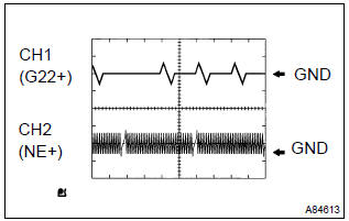
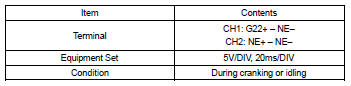
Reference: inspection using the oscilloscope.
Hint
: the correct waveform is as shown on the left.
Monitor description
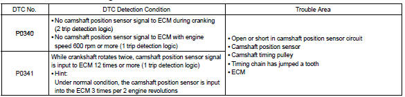
If there is no signal from the camshaft position sensor despite the engine revolving, or if the rotation of the camshaft and the crankshaft is not synchronized, the ecm interprets this as a malfunction of the sensor.
Monitor strategy
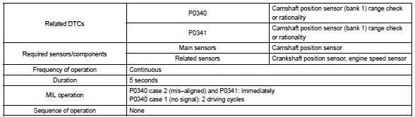
Typical enabling conditions
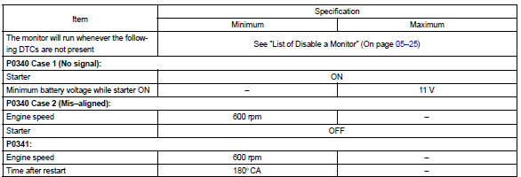
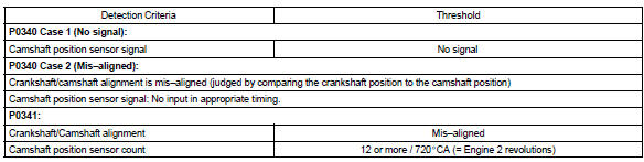
Typical malfunction thresholds
Component operating range

Wiring diagram
Refer to dtc p0335


Other materials:
Inspection procedure
1 Check p/t squib(rh) circuit(airbag sensor assy center – front
seat outer belt assy rh)
Disconnect the negative (–) terminal cable from the battery,
and wait at least for 90 seconds.
disconnect the connectors between the airbag sensor
assy center and the seat belt pretensio ...
Overhaul
1. Remove control shift lever bush
Remove the control shift lever bush from the selecting
bellcrank assy.
2. Remove selecting bellcrank dust cover no.1
Remove the selecting bellcrank dust cover no.1 From the
selecting bellcrank assy.
3. Remove selecting bell crank no.2
...
Inspection procedure
1 Inspect stop lamp switch assy
Check that the stop light lights up when brake pedal is depressed and
turns off when the brake pedal
is released.
2 Inspect skid control ecu terminal voltage(stp terminal)
Disconnect skid control ecu connector.
measure voltage between termina ...