Toyota Corolla (E120) 2002–2008 Repair Manual / Diagnostics / Sfi system / Knock sensor 1 circuit / Circuit description
Toyota Corolla (E120): Circuit description
A flat type knock sensor (non–resonant type) has the structure that can detect the vibration in a wider band of frequency from about 6 khz to 15 khz and has the following features.
Knock sensors are fitted on the cylinder block to detect the engine knocking.
The sensor contains a piezoelectric element which generates a voltage when it becomes deformed, which occurs when the cylinder block vibrates due to knocking. If engine knocking occurs, the ignition timing is retarded to suppress it.
Hint
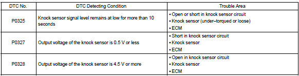
: if the ecm detects the dtc p0325, it enters the fail–safe mode in which the corrective retarded angle value is set to the maximum value.
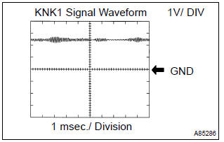
Reference: inspection using the oscilloscope.
- After warming up run the engine at 4,000 rpm, check the waveform between terminal knk1 and eknk of the ecm connector.
Monitor description
The knock sensor, located on the cylinder block, detects spark knock. When spark knock occurs, the sensor picks–up vibrates in a specific frequency range. When the ecm detects the voltage in this frequency range, it retards the ignition timing to suppress the spark knock.
The ecm also senses background engine noise with the knock sensor and uses this noise to check for faults in the sensor. If the knock sensor signal level is too low for more than 10 seconds, and if the knock sensor output voltage is out of normal range, the ecm interprets this as a fault in the knock sensor and sets a dtc.
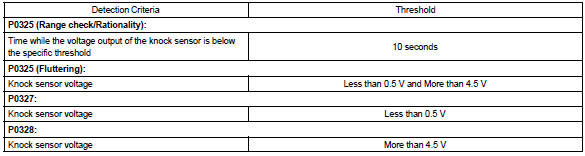
Monitor strategy
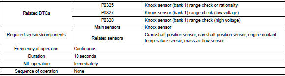
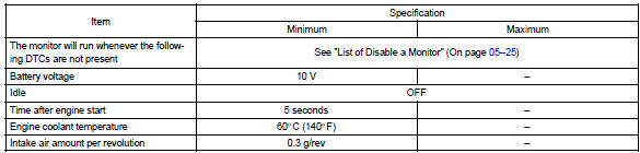
Typical enabling conditions
Typical malfunction thresholds
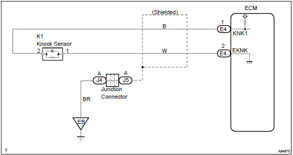
Wiring diagram


Other materials:
Inspection procedure
Hint:
start the inspection from step 1 in case of using the hand–held tester and start
from step 2 in case of not
using the hand–held tester.
1 Read value of hand–held tester(front speed sensor)
Select the datalist mode on the hand–held tester.
check that there is no differe ...
Abbreviations used in this manual
...
Fastening and releasing
the seat belt
To fasten the seat belt, push
the plate into the buckle until
a click sound is heard.
To release the seat belt,
press the release button A.
■Emergency locking retractor
(ELR)
The retractor will lock the belt during
a sudden stop or on impact. It may
also lock if you lean forward too
quickl ...