Toyota Corolla (E120) 2002–2008 Repair Manual / Diagnostics / Sfi system / Oxygen sensor circuit no activity
detected / Circuit description
Toyota Corolla (E120): Circuit description
Refer to dtc p0130
|
Dtc no. |
Dtc detecting condition |
Trouble area |
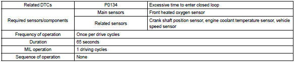
| P0134 | After engine is warmed up, heated oxygen sensor (bank 1
sensor 1) output does not indicate rich (greater than 0.45 V)
even once when conditions (a), (b), (c), (d) and (e) continue for
more than 65 seconds (1 trip detection logic) :
|
|
Hint
: after confirming dtc p0134, check the output voltage of the heated oxygen sensor (bank 1 sensor 1) in the ”diagnosis / enhanced obd ii / data list / all” using the hand-held tester or the obd ii scan tool.
If the output voltage of the heated oxygen sensor is always less than 0.1 V, the sensor circuit may be open or short.
Monitor description
The ecm uses the heated oxygen sensor to optimize the air–fuel mixture in the closed–loop fuel control.
This control helps decrease exhaust emissions by providing the catalyst with a nearly stoichiometric mixture.
The sensor detects the oxygen level in the exhaust gas and the ecm uses this data to control the air–fuel ratio. The sensor output voltage ranges from 0 v to 1 v. If the signal voltage is less than 0.4 V, the air–fuel ratio is lean. If the signal voltage is more than 0.5 V, the air–fuel ratio is rich. If the sensor does not indicate rich even once despite the conditions for the closed–loop fuel control being met and a specified time period has passed, the ecm will conclude that the closed–loop fuel control is malfunctioning. The ecm will illuminate the mil and a dtc is set.
Monitor strategy
Typical enabling condition
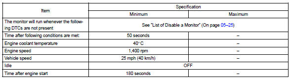
Typical malfunction thresholds

Component operating range

Wiring diagram
Refer to dtc p0130


Other materials:
Tire information
Typical tire symbols
► Full-size tire
► Compact spare tire
1 Tire size
2 DOT and Tire Identification Number (TIN)
3 Uniform tire quality grading
For details, see “Uniform Tire Quality Grading” that follows.
4 Location of treadwear indicators
5 Tire ply composition and ma ...
Replacement
Hint: components:
1. Precaution
2. Disconnect battery negative terminal
3. Remove instrument panel sub–assy lower
Remove the screw from the glove compartment door
stopper sub–assy.
pull the instrument panel sub–assy lower to remove it.
4. Separate passenger airbag co ...
Monitor description
While the engine is being cranked, the battery positive voltage is applied to
terminal sta of the ecm.
If the ecm detects the starter control signal (sta) while the vehicle is
driving, it will conclude that there is
a fault in the starter control circuit. The ecm will turn on the mil and a d ...