Toyota Corolla (E120): Circuit description
Refer to dtc p0115
|
Dtc no. |
Dtc detection condition |
Trouble area |
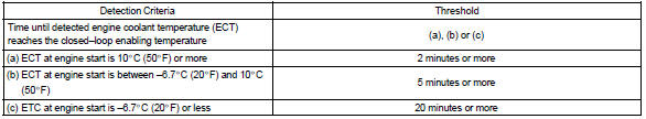
| P0125 | If the engine coolant temperature (ect) was less than –6.6 °C (20 °F) when starting the engine, and 20 minutes after the engine start, the ect sensor still indicates below 20 °C (68 °F) |
|
| If the ect was between –6.6 °C (20 °F) and 10 °C (50 °F) when start, 5 minutes after the start, the ect sensor still indicates below 20 °C (68 °F) | ||
| If the ect was greater than 10 °C (50 °F) when starting the engine, and 2 minutes after the engine start, ect sensor still indicates below 20 °C (68 °F) |
Monitor description
The engine coolant temperature (ect) sensor is used to monitor the temperature of the engine coolant. The resistance of the sensor varies with the actual coolant temperature. The ecm applies a voltage to the sensor and the varying resistance of the sensor causes the signal voltage to vary. The ecm monitors the ect signal voltage after engine start–up. If, after sufficient time has passed, the sensor still reports that the engine is not warm enough for closed–loop fuel control, the ecm interprets this as a fault in the sensor or cooling system.
Example: the engine coolant temperature was 0 c (32 f) at engine start. After 5 minutes running time, the coolant temperature sensor still indicates that the engine is not warm enough to begin air–fuel ratio feedback control.
The ecm interprets this as a fault in the sensor or cooling system and will set a dtc.
Monitor strategy
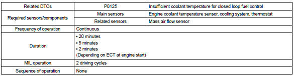
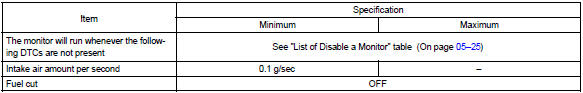
Typical enabling conditions
Typical malfunction thresholds
Wiring diagram
Refer to dtc p0115


Other materials:
Removal & installation and disassembly & reassembly
1. Remove bench type rear seat cushion assy
2. Remove rear floor service hole cover
Remove the rear service hole cover.
Disconnect the fuel pump and vapor pressure sensor
connector.
3. Work for preventing gasoline from spilling out
Start the engine.
after the engi ...
Inspection
1. Inspect outer mirror switch assy
Inspect the mirror switch continuity.
Left side for left/right adjustment switch:
inspect the mirror switch continuity
Standard (left side):
If the result is not as specified, replace the switch assembly.
Right side for left/r ...
Diagnostic trouble code chart
If a dtc is displayed during the dtc check, check the circuit listed in the
table below and proceed to the
page given.
* :● ... Mil light up
...