Toyota Corolla (E120) 2002–2008 Repair Manual / Diagnostics / Sfi system / Engine coolant temperature circuit / Circuit description
Toyota Corolla (E120): Circuit description
A thermistor is built in the engine coolant temperature sensor and changes the resistance value according to the engine coolant temperature.
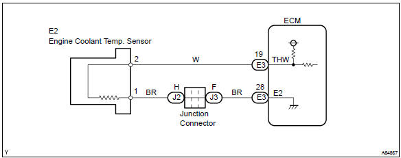
The structure of the sensor and connection to the ecm is the same as those of the intake air temperature sensor.
Hint
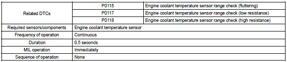
: if the ecm detects the dtc p0115, p0117 or p0118, it operates the fail–safe function in which the engine coolant temperature is assumed to be 80 c (176 °F).
|
Dtc no. |
Proceed to |
Dtc detection condition |
Trouble area |
| P0115 | Step 1 | Open or short in engine coolant temperature sensor circuit for 0.5 Seconds |
|
| P0117 | Step 4 | Short in engine coolant temperature sensor circuit for 0.5 Seconds | |
| P0118 | Step 2 | Open in engine coolant temperature sensor circuit for 0.5 Seconds |
Hint
: after confirming dtc p0115, p0117 or p0118, confirm the engine coolant temperature in the ”diagnosis/ enhanced obd ii/data list/all” using the hand–held tester or the obd ii scan tool.
Monitor description
The engine coolant temperature (ect) sensor is used to monitor the engine coolant temperature. The ect sensor has a thermistor that varies its resistance depending on the temperature of the engine coolant. When the coolant temperature is low, the resistance in the thermistor increases. When the temperature is high, the resistance drops. The variations in resistance are reflected in the voltage output from the sensor. The ecm monitors the sensor voltage and uses this value to calculate the engine coolant temperature. When the sensor output voltage deviates from the normal operating range, the ecm interprets this as a fault in the ect sensor and sets a dtc.
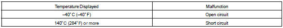
Example: when the ecm calculates that the ect is –40 c (–40 °F), or more than 140 c (284 °F), and if either the condition continues for 0.5 Sec or more, the ecm will set a dtc.
Monitor strategy
Typical enabling conditions

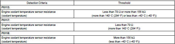
Typical malfunction thresholds
Component operating range

Wiring diagram


Other materials:
On–vehicle inspection
1. Inspect wireless door lock control functions
Hint:
the switch described in this text is a switch for transmitting
signals (lock switch, unlock switch
and panic switch) which is built into the door control transmitter.
All the functions listed below must be checked in the remote contro ...
Circuit description
Refer to dtc p0335
Dtc no.
Dtc detection condition
Trouble area
P0016
Deviation in crankshaft position sensor signal and camshaft
position sensor signal (2 trip detection logic)
Mechanical system (timing chain has jumped a tooth, chain
stretch ...
Selecting, fast-forwarding and reversing tracks/files/songs
■ Selecting a track/file/song
Press the “∧” or “∨” button on “SEEK/TRACK” or turn the “TUNE/ SCROLL” knob
to select the desired track/file/song number.
To fast-forward or reverse, press and hold the “∧” or “∨” button on “SEEK/TRACK”.
...