Toyota Corolla (E120) 2002–2008 Repair Manual / Diagnostics / Sfi system / Mass or volume air flow circuit
range/performance problem / Circuit description
Toyota Corolla (E120): Circuit description
Refer to dtcs p0100
|
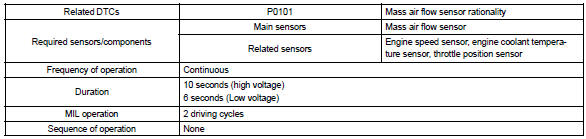
Dtc no. |
Dtc detection condition | Trouble area |
| P0101 | After engine is warmed up, conditions (a) to (d) continue for
more than 10 seconds (2 trip detection logic):
|
|
Conditions (a) and (b) continue for more than 6 seconds: (2 trip
detection logic)
|
Monitor description
The maf (mass air flow) sensor helps the ecm calculates the amount of air flowing through the throttle valve. The ecm uses this information to determine the fuel injection time and provides a proper air–fuel ratio.
Inside the maf sensor, there is a heated platinum wire exposed to the flow of intake air. By applying a specific current to the wire, the ecm heats this wire to a given temperature. The flow of incoming air cools the wire and an internal thermister, changing their resistance. To maintain a constant current value, the ecm varies the voltage applied to these components in the maf sensor. The voltage level is proportional to the air flow through the sensor and the ecm interprets this voltage as the intake air amount. If there is a defect in the sensor or an open or short circuit, the voltage level will deviate outside the normal operating range. The ecm interprets this deviation as a defect in the maf sensor and sets a dtc.
Example: if the voltage is more than 2.2 V at idle, or less than 0.4 V at idle off, the ecm interprets this as a defect in the maf sensor and sets a dtc.
Monitor strategy
Typical enabling conditions
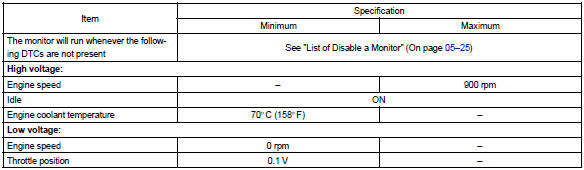
Typical malfunction thresholds

Wiring diagram
Refer to dtc p0100


Other materials:
When the contact is empty
You can transfer the phone numbers in a Bluetooth® phone to the system.
Operation methods differ between PBAP (Phone Book Access Profile) compatible
and PBAP incompatible Bluetooth® phones. If the cellular phone does not support
either PBAP or OPP (Object Push Profile) service, you cannot tra ...
Inspection procedure
1 Inspect stop lamp switch assy
2 Check harness and connector(stop lamp switch assy – ecm)
Install the stop lamp switch assy.
disconnect the ecm connector.
measure the voltage according to the value(s) in the table
below when the brake pedal is depressed and rele ...
Circuit description
The vapor pressure sensor, vsv for canister closed valve (ccv), vsv for
pressure switching valve are used
to detect abnormalities in the evaporative emission control system.
The ecm decides whether there is an abnormality in the evaporative emission
control system based on the
vapor pressur ...