Toyota Corolla (E120) 2002–2008 Repair Manual / Diagnostics / Sfi system / Oxygen sensor heater control
circuit... / Circuit description
Toyota Corolla (E120): Circuit description
Refer to dtc p0130
Hint
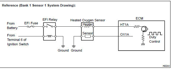
: the ecm provides a pulse width modulated control circuit to adjust current through the heater. The heated oxygen sensor heater circuit uses a relay on the b+ side of the circuit.
Monitor description
The ecm uses the heated oxygen sensor information to regulate the air–fuel ratio close to a stoichiometric ratio. This maximizes the catalytic converter’s ability to purify the exhaust gas. The sensor detects oxygen levels in the exhaust gas and sends this signal to the ecm.
The inner surface of the sensor element is exposed to the outside air. The outer surface of the sensor element is exposed to the exhaust gas. The sensor element is made of the platinum coated zirconia and includes an integrated heating element. The heated oxygen sensor has the characteristic whereby its output voltage change suddenly in the vicinity of the stoichiometric air–fuel ratio. When heated, the sensor becomes very efficient. If the temperature of the exhaust is low, the sensor will not generate useful voltage signals without supplemental heating. The ecm regulates the supplemental heating using a duty–cycle approach to regulate the average current in the heater element. If the heater current is out of the normal range, the sensor’s output signals will be inaccurate and the ecm cannot regulate the air–fuel ratio properly. When the heater current is out of the normal operating range, the ecm interprets this as a malfunction and sets a dtc.
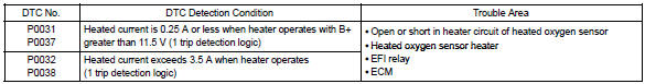
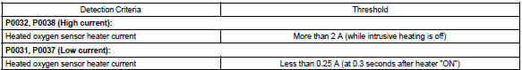
Example: the ecm will set a high current dtc if the current in the sensor is more than 2 a when the heater is off.
Similarly, the ecm will set a low current dtc if the current is less than 0.25 A when the heater is on.
Monitor strategy
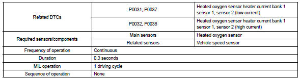
Typical enabling conditions
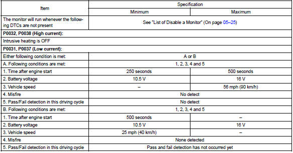
Typical malfunction thresholds
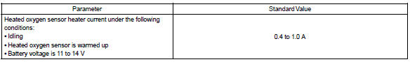
Component operating range
Monitor result (mode 06 data)
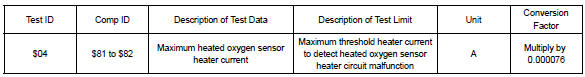
Refer to page 05–27 for detailed information on checking monitor status.
Wiring diagram
Refer to dtc p0130


Other materials:
Side mudguard sub–assy lh
Replacement
Hint:
use the same procedures for the rh side and lh side.
1. Remove side mudguard sub–assy lh
Using a clip remover, remove the 8 retainers and 9 clips.
using a moulding remover, remove the mudguard.
2. Install side mudguard sub–assy lh
Install the mudgu ...
Inspection procedure
Hint:
if dtcs p0115, p0116, p0117, p0118 and p0125 are output
simultaneously, the engine coolant temperature
sensor circuit may be open or short. Perform the troubleshooting of dtc
p0115, p0117 or
p0118 first.
Read freeze frame data using the hand-held tester or the obd ii scan
to ...
Road test
1. Problem symptom confirmation
Taking into consideration the results of the customer problem analysis,
try to reproduce the symptoms
of the trouble. If the problem is that the transaxle does not shift up,
shift down, or the shift point is too
high or too low conduct the following road ...