Toyota Corolla (E120) 2002–2008 Repair Manual / Diagnostics / Sfi system / Crankshaft position – camshaft
position correlation / Circuit description
Toyota Corolla (E120): Circuit description
Refer to dtc p0335
|
Dtc no. |
Dtc detection condition |
Trouble area |
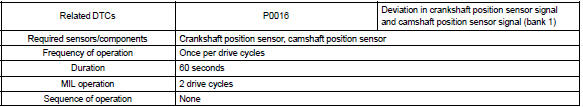
| P0016 | Deviation in crankshaft position sensor signal and camshaft position sensor signal (2 trip detection logic) |
|
Monitor description
The ecm optimizes the valve timing using the variable valve timing (vvt) system to control the intake valve camshaft. The vvt system includes the ecm, the oil control valve (ocv) and the vvt controller. The ecm sends a target ”duty–cycle” control signal to the ocv. This control signal, applied to the ocv, regulates the oil pressure supplied to the vvt controller. The vvt controller can advance or retard the intake valve camshaft.
The ecm calibrates the valve timing of the vvt system by setting the camshaft to the maximum retard angle when the engine speed is idling. The ecm closes the ocv to retard the cam. The ecm stores this valve as ”vvt learned value” (when the difference between the target valve timing and the actual valve timing is 5 or less, the ecm learns it).
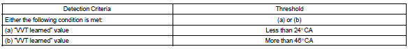
If the learned value meets both of the following conditions (”a” and ”b”), the ecm interprets this as a defect in the vvt system and set a dtc.
- ”vvt learning” value is less than 24 ca, or more than 46 ca.
- above condition continues for more than 18 seconds.
Monitor strategy
Typical enabling conditions
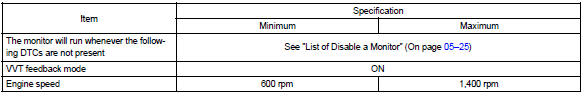
Typical malfunction thresholds
Wiring diagram
Refer to dtc p0335


Other materials:
Inspection procedure
1 Check front airbag sensor (lh) circuit (to b+)(airbag sensor assy
center – airbag sensor front lh)
Disconnect the negative (–) terminal cable from the battery,
and wait at least for 90 seconds.
disconnect the connectors between the airbag sensor
assy center and the airbag ...
Precaution
1. Handling precautions on srs airbag system
The vehicle is equipped with srs (supplemental restraint system) such as
the driver airbag and front
passenger airbag. Failure to carry out service operation in correct sequence
could cause the srs to
unexpectedly deploy during servicing, po ...
Cooling
Preparation
Recomended tools
Equipment
Coolant
...