Toyota Corolla (E120) 2002–2008 Repair Manual / Diagnostics / Sfi system / Camshaft position ”a” –timing over / Circuit description
Toyota Corolla (E120): Circuit description
Refer to dtc p0010
|
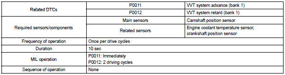
Dtc no. |
Dtc detection condition |
Trouble area |
| P0011 | Condition (a) or (b) continues after engine is warmed up and
engine speed at 550 to 4,000 rpm (problem of the advanced
ocv):
|
|
| P0012 | Condition (a) or (b) continues after engine is warmed up and
engine speed at 550 to 4,000 rpm (problem of the retarded
ocv):
|
Monitor description
The ecm optimizes the valve timing using the variable valve timing (vvt) system to control the intake valve camshaft. The vvt system includes the ecm, the oil control valve (ocv) and the vvt controller. The ecm sends a target ”duty–cycle” control signal to the ocv. This control signal, applied to the ocv, regulates the oil pressure supplied to the vvt controller. The vvt controller can advance or retard the intake valve camshaft.
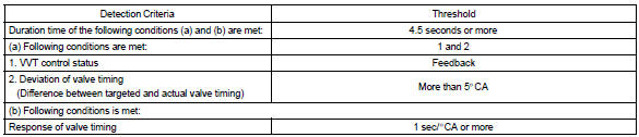
Example: when a difference between the targeted and actual valve timing is more than 5 camshaft angle ”ca” and this condition continues for more than 4.5 Sec, and if the ocv is forcibly activated 63 times or more.
Advanced cam dtcs are subject to ”1 trip” detection logic.
Retarded cam dtcs are subject to ”2 trip” detection logic.
Monitor strategy
Typical enabling conditions
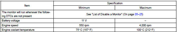
Typical malfunction thresholds
Wiring diagram
Refer to dtc p0010


Other materials:
Body panel sealing areas
Be sure to apply body sealer to the body panel joints and door edges (tip of
outer panel folded part), etc., To waterproof
and rustproof them.
Hint:
apply degreasing agent to a clean cloth and clean the sealer
application areas.
After removing the applied spot sealer from the se ...
Overhaul
1. Remove roof headlining assy
2. Remove sliding roof glass sub–assy
using a torx wrench (t25), remove the 4 screws the sliding roof
glass.
pull the glass upward to remove it.
3. Remove sliding roof weatherstrip
4. Remove sliding roof drive gear sub–assy
Notice:
...
Playing an audio CD and MP3/WMA/AAC discs (Multimedia system)
CD player operation
Insert disc or select “CD” on the audio source selection screen with a disc
inserted to begin listening to a CD.
Audio control screen
Pressing the “AUDIO” button displays the audio control screen from any screens
of the selected source.
1 Audio source selection sc ...