Toyota Corolla (E120) 2002–2008 Repair Manual / Diagnostics / Sfi system / Camshaft position ”a” actuator
circuit / Circuit description
Toyota Corolla (E120): Circuit description
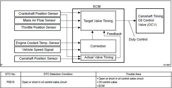
The variable valve timing (vvt) system includes the ecm, the oil control valve (ocv) and the vvt controller.
The ecm sends a target ”duty–cycle” control signal to the ocv. This control signal, applied to the ocv, regulates the oil pressure supplied to the vvt controller. Camshaft timing control is performed based on engine operation conditions such as the intake air volume, throttle position and engine coolant temperature.
The ecm controls the ocv, based on the signals output from the sensors. The vvt controller regulates the intake camshaft angle using oil pressure through the ocv. As result, the relative position between the camshaft and the crankshaft is optimized, and the engine torque improves, fuel economy improves, and exhaust emissions decrease under overall driving conditions. Also, the ecm detects the actual valve timing using signals from the camshaft position sensor and the crankshaft position sensor, and performs the feedback control. This is how target valve timing is verified by the ecm.
Monitor description
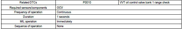
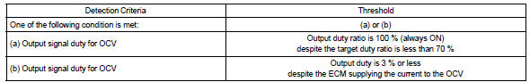
After the ecm sends the ”target” duty–cycle signal to the ocv, the ecm monitors the ocv current to establish an ”actual” duty–cycle. The ecm detects a malfunction and sets a dtc when the actual duty–cycle ratio varies from the target duty–cycle ratio.
Monitor strategy
Typical enabling conditions
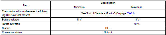
Typical malfunction thresholds
Component operating ra

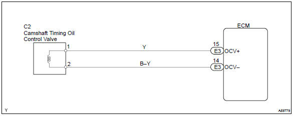
Wiring diagram


Other materials:
Turning on light switch does not light up night time
illumination of radio receiver
Wiring diagram
Inspection procedure
1 Inspect radio receiver assy(ill+, ill–)
Check that the voltage between terminals at each condition,
as shown in the chart.
Standard:
Repair or replace harness or connector ...
Manual transmission / transaxle
Service data
Torque specification
...
Deleting a registered phone number
1 Select “Delete contacts” using .
2 Select the desired phone number using
and press
(YES).
To delete all of the registered phone numbers, select “All delete” using
and press
(YES). ...