Toyota Corolla (E170) 2014–2019 Owners Manual / Driving / Driving procedures / Engine (ignition) switch (vehicles with a smart key system) / Changing engine switch modes
Toyota Corolla (E170): Changing engine switch modes
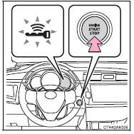
Modes can be changed by pressing the engine switch with the brake pedal (continuously variable transmission) or clutch pedal (manual transmission) released. (The mode changes each time the switch is pressed.)
► Vehicles without a multi-information display Off*
The emergency flashers can be used.
The smart key system indicator light (green) is off.
ACCESSORY mode
Some electrical components such as the audio system can be used.
The smart key system indicator light (green) flashes slowly.
IGNITION ON mode
All electrical components can be used.
The smart key system indicator light (green) flashes slowly.
*: Vehicles with a continuously variable transmission: If the shift lever is in a position other than P when turning off the engine, the engine switch will be turned to ACCESSORY mode, not to off.
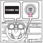
► Vehicles with a multi-information display Off*
The emergency flashers can be used.
The multi-information display will not be displayed.
ACCESSORY mode
Some electrical components such as the audio system can be used.
“POWER ON” will be displayed on the multi-information display.
IGNITION ON mode
All electrical components can be used.
“POWER ON” will be displayed on the multi-information display.
*: Vehicles with a continuously variable transmission: If the shift lever is in a position other than P when turning off the engine, the engine switch will be turned to ACCESSORY mode, not to off.


Other materials:
What to do if... (Troubleshooting)
If you have a problem, check the following before contacting your Toyota dealer.
The doors cannot be locked, unlocked, opened or closed
You lose your keys
● If you lose your keys or mechanical keys, new genuine keys or mechanical keys
can be made by your Toyota dealer.
● If you lo ...
Meter display
■ Locations of gauges and meters
Engine coolant temperature gauge
Displays the engine coolant temperature
Outside temperature
Displays the outside temperature within the range of -40ºF (-40ºC) to 140ºF
(60ºC)
Analog speedometer/Tachometer
This setting can be changed on the setting scr ...
Inspection procedure
1 Check p squib circuit(airbag sensor assy center – instrument
panel passenger airbag assy)
Disconnect the negative (–) terminal cable from the battery,
and wait at least for 90 seconds.
disconnect the connectors between the airbag sensor
assy center and the instrument panel ...