Toyota Corolla (E120) 2002–2008 Repair Manual / Diagnostics / Audio system / Cd cannot be inserted or is ejected right after
insertion
Toyota Corolla (E120): Cd cannot be inserted or is ejected right after insertion
Wiring diagram
Inspection procedure
1 Check if a proper cd is inserted
- Check that a proper cd is inserted.
- Make sure that the cd is normal audio cd, and that there is no
deformation, flaw, stain, burr and
other defects on the cd.
Standard: normal audio cd.
Reference:
- translucent or different–shaped cd cannot be played.
- Cd–rom for personal computers (with music recorded in) and recorded cd–r may not be played.
- Playing an 3.2 In. (8–Cm) cd does not require an adapter.


2 Check that a proper cd is inserted
- Check that a proper cd is inserted.
- Check whether or not the cd is inserted upside down.
Standard: not upside down.


3 Disc cleaning
- Disk cleaning
- if the disk gets dirty, clean the disk by wiping the surface from the center to outside in the radial directions with a soft cloth.
Notice
: do not use a conventional record cleaner or anti–static preservative.


4 Replace cd with another and recheck
- Replace the cd with another and recheck.
- Replace the faulty cd with the normal one to see if the same
trouble occurs again.
Standard: malfunction disappear.


5 Check if radio auto–search functions properly
- Check if the radio auto–search function properly.
- Perform the auto–research of the radio and check that the
operation is normal.
Standard: malfunction disappear.

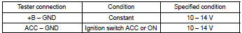
6 Inspect radio receiver assy(+b, acc, gnd)
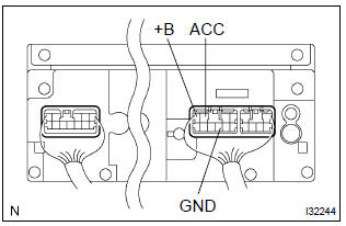
- Check that the continuity between terminals at each condition, as shown in the chart.
Standard:

- Check that the voltage between terminals at each condition, as shown in the chart.
Standard:

Repair or replace harness or connector


Other materials:
Engine rear oil seal
Replacement
1. Remove manual transaxle assy (m/t transaxle)
2. Remove automatic transaxle assy (a/t transaxle)
3. Remove clutch cover assy (m/t transaxle)
remove the 6 bolts and clutch cover.
4. Remove clutch disc assy (m/t transaxle)
5. Remove flywheel sub–assy (m/t transaxle ...
Circuit description
While driving uphill with cruise control activated, in order to minimize gear
shifting and provide smooth cruising
overdrive may be prohibited temporarily under some conditions.
The cruise control ecu sends o/d cut signals to the ecm as necessary and the ecm
cancels overdrive
shifting until ...
Disposal
1. Dispose shock absorber assy rear lh
Fully extend the shock absorber rod.
using a drill, make a hole in the cylinder as shown in the
illustration to discharge the gas inside.
Caution:
when drilling, chips may fly out, work carefully.
The gas is colorless, odorless and no ...