Toyota Corolla (E120) 2002–2008 Repair Manual / Diagnostics / Sfi system / Readiness monitor drive pattern / Catalyst monitor (o2s type)
Toyota Corolla (E120): Catalyst monitor (o2s type)
- Preconditions
The monitor will not run unless:
- mil is off.
- Engine coolant temperature (ect) is 176°f (80 °C) or greater.
- Intake air temperature (iat) is 14°f (–10 °C) or greater.*
Notice
: * 2002 and later my vehicles: the readiness test can be completed in cold ambient conditions (less than 14°f / –10 °C), if the drive pattern is repeated a second time after cycling the ignition off.
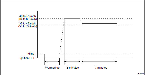
- Drive pattern
- connect the obd ii scan tool to the dlc3 to check monitor status and preconditions.
- Drive the vehicle at 40 to 55 mph (64 to 88 km/h) for approximately 3 minutes.
Notice
: drive with smooth throttle operation and avoid sudden acceleration.
If iat is less than 50°f (10 °C) when starting engine, continue to drive vehicle at 40 to 55 mph (64 to 88km/h) for approximately 4 minutes.
- Drive the vehicle at 35 to 45 mph (56 to 72 km/h) for approximately 7 minutes.
Notice
: drive with smooth throttle operation and avoid sudden deceleration as much as possible with the throttle fully closed.
- If readiness status dose not switch to complete, make sure that the preconditions are met and the ignition switch is turned off and then repeat steps (2) and (3).
- Release pressure in the fuel tank by removing and then reinstalling the fuel tank cap.
- Start the engine and immediately begin driving as directed.


Other materials:
Inspection procedure
Hand–held tester:
1 Perform active test by hand–held tester(operation of circuit
opening relay)
Connect the hand–held tester to the dlc3.
turn the ignition switch on and push the hand–held tester main
switch on.
select the item ”diagnosis / enhanced obd ii / active ...
Oxygen sensor monitor (front and rear o2s system)
Preconditions
The monitor will not run unless:
mil is off
drive pattern
connect the obd ii scan tool to the dlc3 to check monitor status
and preconditions.
Start the engine and allow it to idle for 2 minutes or more.
Drive the vehicle at 25 mph ...
Folding the mirrors
Push the mirror back in the direction of the vehicle’s rear.
■Mirror angle can be adjusted when
► Vehicles without a smart key system
The engine switch is in the “ACC” or “ON” position.
►Vehicles with a smart key system
The engine switch is in ACCESSORY or IGNITION ...