Toyota Corolla (E120): System description
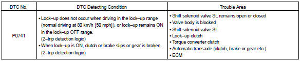
The ecm uses the signals from the throttle position sensor, air–flow meter and crankshaft position sensor to monitor the engagement condition of the lock–up clutch.
Then the ecm compares the engagement condition of the lock–up clutch with the lock–up schedule in the ecm memory to detect mechanical trouble of the shift solenoid valve sl, valve body and torque converter clutch or automatic transaxle (clutch, brake or gear etc.).
Monitor description
Based on the signals from the throttle position sensor, the airflow meter and the crankshaft position sensor, the ecm sends a signal to the shift solenoid valve sl to regulate the hydraulic pressure and provide smoother gearshifts. The shift–solenoid valve sl responds to commands from the ecm. The valve controls the lock–up relay valve to perform torque–converter lock–up and flexible lock–up functions.
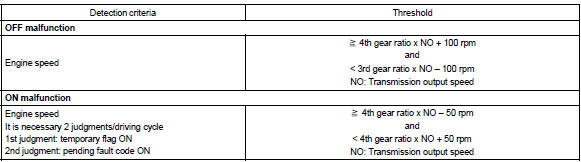
The ecm compares the engine rpm (ne) signal and the input speed calculated by output speed sensor (output speed) and gear ratio to detect torque converter lock–up. The ecm then compares the lock–up status against the lock–up schedule in the ecm memory. If the ecm does not detect lock–up at the appropriate time, it will conclude that there is a malfunction of shift solenoid sl. The ecm will illuminate the mil.
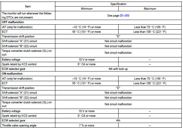
Monitor strategy
Typical enabling condition
Typical malfunction thresholds


Other materials:
Overhaul
1. Remove bench type rear seat cushion assy
Disengage the 2 clamps, and then remove the seat cushion.
2. Remove separate type rear seat back assy
lean the seat back forward.
remove the 2 clips.
remove the 2 bolts and seat back lh.
employ the same manner describ ...
Inspection
1. Windshield wiper switch assy
Continuity check
check the continuity of each terminal of the connector.
Front wiper switch
Standard:
Front washer switch
Standard:
W/o intermittent time adjust:
intermittent operation check
connect the voltmeter (+) te ...
How to proceed with troubleshooting
The hand–held tester can be used at step 3, 4, 6, 9.
1 Vehicle brought to workshop
2 Customer problem analysis
3 Connect the obd ii scan tool or hand–held tester to dlc3
4 Check and clear dtc and freeze frame data
5 Visual inspection
6 Setting the check mode diagnosis
7 Proble ...