
Toyota Corolla (E120): Replacement
1. Remove instrument panel sub–assy lower
2. Remove clutch pedal spring
3. Remove clutch master cylinder push rod clevis w/hole pin
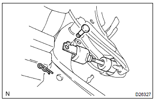
- Remove the clip and hole pin.
4. Remove clutch pedal support sub–assy
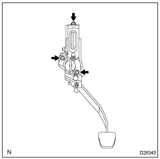
- W/ cruise control: disconnect the clutch switch assy connector.
- disconnect the clutch start switch assy connector.
- remove the 2 nuts, bolt and clutch pedal support assy.
5. Remove clutch pedal sub–assy
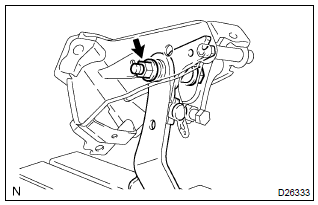
- Remove the bolt and nut.
- remove the clutch pedal sub–assy from the clutch pedal support.
6. Remove clutch pedal pad
7. Remove clutch pedal bush
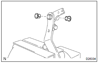
- Remove the 2 bushes from the clutch pedal.
8. Remove clutch pedal no.1 Cushion
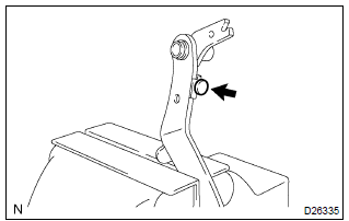
- Using needle–nose pliers, remove the no.1 Cushion from the clutch pedal.
9. Remove clutch master cylinder push rod clevis bush
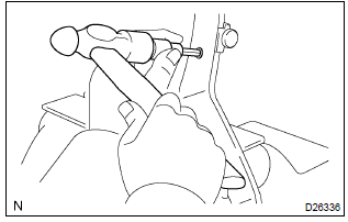
- Using a 8 mm hexagon wrench and a hammer, remove the clevis bush from the clutch pedal sub–assy.
10. Install clutch master cylinder push rod clevis bush
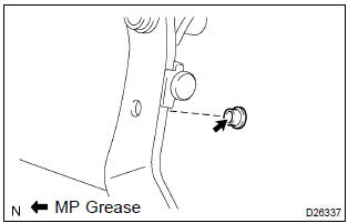
- Apply mp grease to inside of a new clevis bush.
- install the clevis bush to the clutch pedal.
Hint
: install the clevis bush from the right side of the vehicle.
11. Install clutch pedal no.1 Cushion
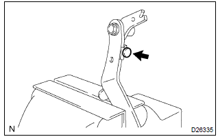
- Using needle–nose pliers, install the no.1 Cushion to the clutch pedal
12. Install clutch pedal bush
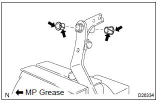
- Apply mp grease to both side of 2 new bushes.
- install the 2 bushes to the clutch pedal.
13. Install clutch pedal pad
14. Install clutch pedal sub–assy
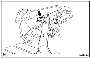
- Install the clutch pedal sub–assy to the clutch pedal support
with the bolt and nut.
Torque: 36.8 Nvm (375 Kgf·cm, 27 ft·lbf)
Hint
: install the bolt from the right side of the vehicle. 15. Install clutch pedal support sub–assy
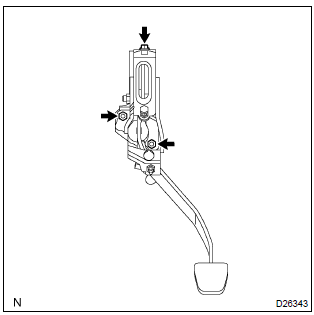
- Install the clutch pedal support to the vehicle with the 2
nuts and bolt.
Torque:
bolt: 19.1 Nvm (195 Kgf·cm, 14 ft·lbf) nut: 11.8 Nvm (120 Kgf·cm, 9 ft·lbf) - connect the clutch start switch assy connector.
- w/ cruise control: connect the clutch switch assy connector.
16. Install clutch master cylinder push rod clevis w/hole pin
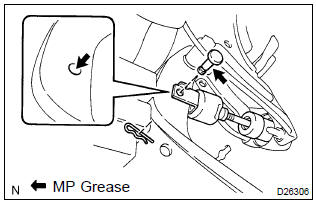
- Apply mp grease to the contact surface of the hole pin and clevis bush.
- connect the clevis to the clutch pedal sub–assy with the
hole pin.
Hint
: install the hole pin from the right side of the vehicle.
- install the clip to the hole pin.
17. Install clutch pedal spring
18. Install instrument panel sub–assy lower
19. Inspect srs warning light
20. Inspect and adjust clutch pedal sub–assy


Other materials:
Circuit description
The airbag front rh sensor circuit consists of the airbag sensor assy center
and airbag front rh sensor.
Dtc b1156/b1157/15 is recorded when a malfunction is detected in the airbag
front rh sensor circuit.
Wiring diagram
...
Check mode procedure
1. Dtc check (check mode)
Hint:
hand–held tester only:
compared to the normal mode, the check mode has more sensing
ability to detect malfunctions. Furthermore, the same diagnostic
items which are detected in the normal mode can also be
detected in the check mode.
Procedure for check m ...
Calibrating the compass
The direction display deviates from
the true direction determined by the earth’s magnetic field. The amount of deviation
varies according to the geographic position of the vehicle.
If you cross over a map boundary shown in illustration, the compass will deviate.
To obtain higher precision or ...