Toyota Corolla (E120): Replacement
1. Remove hood sub–assy
2. Remove cylinder head cover no.2
3. Remove battery
4. Remove battery carrier
- Remove the 4 bolts and battery carrier.
5. Remove air cleaner assembly with hose
6. Remove floor shift cable transmission control shift
- Remove the nut from the control shaft lever.
- disconnect the control cable from the control shaft lever.
- remove the clip and disconnect the control cable from the control cable bracket.
7. Remove transmission control cable support
- Disconnect the wire harness clamp and control cable from the control cable support.
- remove the bolt and control cable support.
8. Remove transmission control cable bracket no.1
- remove the 2 bolts and control cable bracket.
9. Disconnect wire harness
- Remove the 2 bolts and disconnect the 2 wire harnesses.
- remove the bolt and disconnect the wire harness clamp bracket.
- Remove the bolt and disconnect the wire harness clamp bracket.
10. Disconnect connector
- disconnect the transmission wire connector.
- disconnect the park/neutral position switch connector.
- w/o abs: disconnect the speedometer sensor connector.
11. Remove transmission oil filler tube sub–assy
- Remove the atf lever gauge.
- remove the 2 bolts, oil cooler tube clamp and oil filler tube.
- remove the o–ring from the oil filler tube.
12. Disconnect oil cooler inlet tube no.1
- Using sst, disconnect the oil cooler inlet tube no. 1.
Sst 09023–12700
13. Disconnect oil cooler outlet tube no.1
- using sst, disconnect the oil cooler outlet tube no. 1.
Sst 09023–12700
14. Disconnect oxygen sensor connector
- remove the foot rest.
- pull up the floor carpet.
- disconnect the oxygen sensor connector.
15. Suspend engine assy
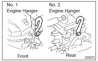
- Disconnect the 2 pcv hoses.
- install the no.1 And no.2 Engine hangers in the correct
direction.
Parts no.:
No.1 Engine hanger: 12281–22021 no.2 Engine hanger: 12281–15040 bolt: 91512–b1016 torque: 38 nvm (387 Kgf·cm, 28 ft·lbf) - attach the engine chain hoist to the engine hangers.
Caution
: do not attempt to hang the engine by hooking the chain to any other parts.
16. Remove front wheels
17. Remove engine under cover rh
18. Remove engine under cover lh
19. Drain automatic transaxle fluid
- remove the drain plug and gasket, and drain atf.
- install a new gasket and drain plug.
Torque: 17.5 Nvm (178 Kgf·cm, 13 ft·lbf)
20. Remove exhaust pipe assy front
21. Remove front drive shaft assy rh
sst 09520–01010, 09520–24010 (09520–32040)
22. Remove front drive shaft assy lh
sst 09520–01010, 09520–24010 (09520–32040)
23. Remove automatic transmission case protector
- remove the 2 bolts and case protector.
24. Remove starter assy
- remove the nut and disconnect the starter wire.
- disconnect the connector.
- remove the 2 bolts and starter.
25. Support automatic transaxle assy
- support the automatic transaxle with a transmission jack.
26. Remove transverse engine engine mounting insulator
- Remove the 5 bolts, nut and engine mounting insulator lh.
31. Remove transverse engine engine mounting bracket
- Remove the 2 bolts and engine mounting bracket fr.
32. Remove transverse engine engine mounting bracket
- Remove the 3 bolts and engine mounting bracket rr.
33. Remove flywheel housing under cover
34. Remove automatic transaxle assy
- Turn the crankshaft to gain access and remove the 6 bolts while holding the crankshaft pulley bolt with a wrench.
- Remove the 6 bolts.
- separate and remove the automatic transaxle.
35. Remove torque converter clutch assy
36. Inspect torque converter clutch assy
sst 09350–32014 (09351–32010, 09351–32020)
37. Install torque converter clutch assy
- Install the torque converter clutch to the automatic transaxle.
- using vernier calipers, measure the dimension ”a” between the transaxle fitting part and the converter fitting part of the drive plate.
- Using vernier calipers and a straight edge, measure the
dimension ”b” shown in the illustration and check that ”b”
is greater than ”a” measured in (b).
Standard: a + 1 mm or more
Notice
: do not add the thickness of straight edge.
38. Install automatic transaxle assy
- Install the automatic transaxle and 6 bolts to the engine.
Torque:
bolt a: 64 nvm (650 Kgf·cm, 47 ft·lbf) bolt b: 46 nvm (470 Kgf·cm, 34 ft·lbf) bolt c: 23 nvm (235 Kgf·cm, 17 ft·lbf)
- Install the 6 torque converter mounting bolts.
Torque: 28 nvm (285 Kgf·cm, 20 ft·lbf)
Hint
: first install yellowish green colored bolt and then the 5 bolts.
39. Install flywheel housing under cover
40. Install transverse engine engine mounting bracket
- Install the engine mounting bracket rr and 3 bolts to the
automatic transaxle.
Torque: 64 nvm (652 Kgf·cm, 47 ft·lbf)
41. Install transverse engine engine mounting bracket
- Install the engine mounting bracket fr and 2 bolts to the
automatic transaxle.
Torque: 64 nvm (652 Kgf·cm, 47 ft·lbf)
42. Install engine mounting member sub–assy center
- Install the dynamic damper, member sub–assy center
with engine mounting insulator fr and 4 bolts.
Torque:
bolt a: 39 nvm (398 Kgf·cm, 29 ft·lbf) bolt b: 52 nvm (530 Kgf·cm, 38 ft·lbf)
43. Install transverse engine engine mounting insulator
- Install the engine mounting insulator rr and bolt to the
engine mounting bracket rr.
Torque: 87 nvm (887 Kgf·cm, 64 ft·lbf)
- Tighten the 3 nuts and bolt.
Torque: 52 nvm (530 Kgf·cm, 38 ft·lbf)
44. Install transverse engine engine mounting bracket
- Install the engine mounting bracket lh and 3 bolts to the
automatic transaxle.
Torque: 52 nvm (530 Kgf·cm, 38 ft·lbf)
45. Install transverse engine engine mounting insulator
- Install the engine mounting insulator lh, 5 bolts and nut.
Torque:
bolt a: 52 nvm (530 Kgf·cm, 38 ft·lbf) bolt b: 80 nvm (815 Kgf·cm, 59 ft·lbf) nut b: 80 nvm (815 Kgf·cm, 59 ft·lbf)
46. Install transverse engine engine mounting insulator
- Install the bolt and nut to the engine mounting bracket fr.
Torque: 52 nvm (530 Kgf·cm, 38 ft·lbf)
47. Install starter assy
- install the starter and 2 bolts.
Torque: 39 nvm (400 Kgf·cm, 29 ft·lbf)
-
connect the connecter.
- install the starter wire and nut.
Torque: 13 nvm (132 Kgf·cm, 10 ft·lbf)
48. Install automatic transmission case protector
- install the case protector with the 2 bolts.
Torque: 18 nvm (182 Kgf·cm, 14 ft·lbf)
49. Install front drive shaft assy lh
50. Install front drive shaft assy rh
51. Install exhaust pipe assy front
52. Install engine under cover lh
53. Install engine under cover rh
54. Install front wheels
torque: 103 nvm (1,050 Kgf·cm, 76 ft·lbf)
55. Install oxygen sensor connector
- connect the oxygen sensor connector.
- install the floor carpet and foot rest.
56. Install transmission oil filler tube sub–assy
- Temporarily install the oil cooler outlet tube no. 1.
- temporarily install the oil cooler inlet tube no. 1.
- coat a new o–ring with atf, and install them to the oil filler tube.
- install the oil filler tube to the automatic transaxle.
- Install the oil cooler tube clamp and 2 bolts.
Torque: 5.5 Nvm (56 Kgf·cm, 49 in.Vlbf)
- install the atf lever gauge.
57. Install oil cooler inlet tube no.1
- Using sst, tighten the oil cooler inlet tube no. 1.
Sst 09023–12700
torque: 34.5 Nvm (350 Kgf·cm, 25 ft·lbf)
58. Install oil cooler outlet tube no.1
- using sst, tighten the oil cooler outlet tube no. 1.
Sst 09023–12700
torque: 34.5 Nvm (350 Kgf·cm, 25 ft·lbf)
59. Connect connector
- connect the transmission wire connector.
- connect the park/neutral position switch connector.
- w/o abs: connect the speedometer sensor connector.
60. Install wire harness
- Install the wire harness clamp bracket and bolt.
Torque: 12.75 Nvm (130 Kgf·cm, 9 ft·lbf)
- Install the wire harness clamp bracket and 2 wire harnesses
with the 3 bolts.
Torque:
bolt a: 25.5 Nvm (260 Kgf·cm, 19 ft·lbf) bolt b: 10 nvm (102 Kgf·cm, 7 ft·lbf) bolt c: 13 nvm (132 Kgf·cm, 10 ft·lbf)
61. Install transmission control cable bracket no.1
- install the control cable bracket and 2 bolts.
Torque: 12 nvm (122 Kgf·cm, 9 ft·lbf)
62. Install transmission control cable support
- Install the control cable support and bolt.
Torque: 12 nvm (122 Kgf·cm, 9 ft·lbf)
- connect the control cable and wire harness to the control cable support.
63. Install floor shift cable transmission control shift
- Temporarily install the control cable to the control shaft lever with the nut.
- install the control cable and clip to the bracket.
64. Install battery carrier
- Install the battery carrier and 4 bolts.
Torque: 13 nvm (132 Kgf·cm, 10 ft·lbf)
65. Install air cleaner assembly with hose
torque: 7.0 Nvm (71 Kgf·cm, 62 in.Vlbf)
66. Install cylinder head cover no.2
Torque: 7.0 Nvm (71 Kgf·cm, 62 in.Vlbf)
67. Install hood sub–assy
torque: 13 nvm (130 Kgf·cm, 10 ft·lbf)
68. Inspect hood sub–assy
69. Adjust hood sub–assy
70. Add automatic transaxle fluid
71. Inspect automatic transaxle fluid
72. Adjust shift lever position
73. Inspect shift lever position
74. Inspect front wheel ariment
75. Check abs speed sensor signal (w/ abs)


Other materials:
Toyota Safety Sense 3.0
The Toyota Safety Sense 3.0
consists of the driving
assist systems and contributes
to a safe and comfortable
driving experience:
WARNING
■Toyota Safety Sense 3.0
The Toyota Safety Sense 3.0
operates under the assumption
that the driver will drive safely,
and is designed to help reduce
the impact t ...
Automatic transaxle fluid (atm)
On–vehicle inspection
1. Check the fluid level
Hint:
drive the vehicle so that the engine and transaxle are at normal
operating temperature.
Fluid temperature: 70 – 80 °c (158 – 176 °f)
park the vehicle on a level surface and set the parking
brake.
with the engin ...
Source voltage drop
The srs is equipped with a voltage–increase circuit (dc–dc converter) in the
airbag sensor assy center
in case the source voltage drops.
When the battery voltage drops, the voltage–increase circuit (dc–dc converter)
functions to increase the
voltage of the srs to normal voltage.
...